Power rail: verschil tussen versies
| (7 tussenliggende versies door 4 gebruikers niet weergegeven) | |||
| Regel 1: | Regel 1: | ||
| + | [[Category:Historic projects]] | ||
= Project scope = | = Project scope = | ||
| Regel 49: | Regel 50: | ||
= Sketch code = | = Sketch code = | ||
| − | < | + | <pre> |
/*************************************************** | /*************************************************** | ||
Adafruit MQTT Library ESP8266 modified example (Alex Yanson 2017) | Adafruit MQTT Library ESP8266 modified example (Alex Yanson 2017) | ||
| Regel 189: | Regel 190: | ||
digitalWrite(ledPin, LOW); // Switch the status LED on continuously if MQTT is connected | digitalWrite(ledPin, LOW); // Switch the status LED on continuously if MQTT is connected | ||
} | } | ||
| − | </ | + | </pre> |
Huidige versie van 28 okt 2024 om 20:48
Inhoud
[verbergen]Project scope
After comissioning the 230V power rail on the back wall of the "3d-printer" room, an idea came about of making it remote-controlled for an easy remote poweroff. Taking into account potential scaling up to other nodes at MSL, where there may be no line-of-sight access for radio- or IR-remote, a decision was made to use MQTT over WiFi with ESP8266 as hardware.
Both L and N wires were to be switched independently, so two relays capable of switching 16A @ 230Vac were needed. These commonly come with coil voltages of 12Vdc and higher.
At the same time, ESP8266 runs nominally on 3.3V, but takes 5V via a LM1777 3.3v regulator. Going higher (to 12Vdc) was considered not recommended, as the SMD regulator would then dissipate too much heat.
Implementation
Meeting both requirements above, we went with Fujitsu K1CK005W 5Vdc relays [1], while the SLA-05VDC-SL-A relays from AliExpress [2] were in transit. This way, we need only one 230Vac->5Vdc supply for both the ESP and the relays.
For this purpose, HLK-PM01 power brick [3], delivering 3W, was sufficient (~1W for ESP, plus ~1W per relay).
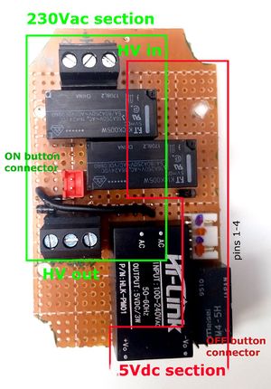
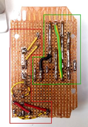
As the implementation for the power rail in the printer room uses double-through Fujitsu relays, their contacts are connected in parallel to reduce the current load. The HV and LV areas are separated as much as possible. In order to have this working with or without the ESP, the latter was put on a connector. A shunt (pin1-3 and pin2-4 shorted) can be used to have it working without ESP (on-off by front panel buttons only).
Schematic
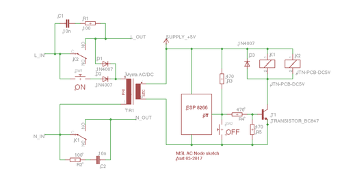
The original schematic is done by Aart (thx!):
As the action of the OFF button needs to be reversed ("switch when released"), an extra 5V relay is added. Also the snubbers are removed to prevent 230V leakage when the relays are off.
Build
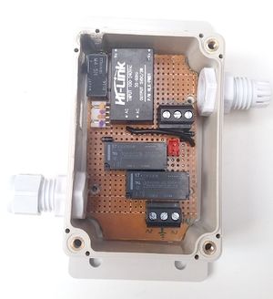
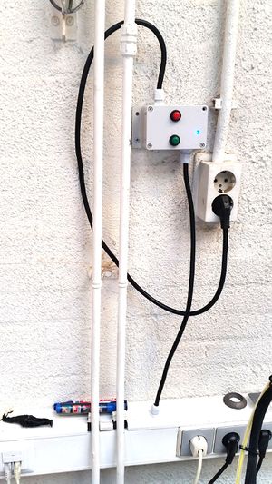
This is fitted in a box, fitted with 1.5mm^2 power cables, and mounted on the wall. Note that the screw terminals for the power cables must be rated to 16A [4]
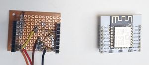
The ESP control unit plugs into the white connector with blue and red dots on Fig1. Pin1 is +5V, pin2 is GND, pin3 is Relay+5V, pin4 is relay return. Relay coils require more current than a GPIO pin of ESP can deliver, so a transistor is used on the ESP print to boost the switching current to pins 3-4 on the white connector.
MQTT communication
The code for ESP is written in Arduino IDE and uses Adafruit_MQTT libraries.
It creates two feeds: makerspace/powerrail (feed1) and makerspace/powerrail/status (feed2), writes "ON" to both feeds and "Power rail is ON" to feed1. When "OFF" is posted to feed1, it posts "Power rail is OFF" to feed1, "OFF" to feed2, and shuts down. If after 10sec it is still not off (stuck relay?), it will post an error message to feed1.
It is only possible to switch the power on by hand, pressing the green button on the box.
Sketch code
/***************************************************
  Adafruit MQTT Library ESP8266 modified example (Alex Yanson 2017)
  Chinese ESP8266,

  ESP powers on, connects to MQTT, and waits for OFF signal to switch power off via GPIO5

  This code uses blue LED of ESP (GPIO2) for indicating status:
  Blink (1 sec) - only power is on
  Slow blink (5 sec) - power and WiFi are there, MQTT is missing (see COM output as to why)
  Always on - normal operation: power, WiFi and MQTT are all connected
 ****************************************************/
#include <ESP8266WiFi.h>
#include "Adafruit_MQTT.h"
#include "Adafruit_MQTT_Client.h"

/************************* WiFi Access Point *********************************/
#define WLAN_SSID       "SSID of MSL IoT network"
#define WLAN_PASS       "PWD for the MSL IoT network"

/************************* makerspaceleiden Setup *********************************/
#define AIO_SERVER      "makerspaceleiden.nl"
#define AIO_SERVERPORT  1883                   //
#define AIO_USERNAME    ""                     // No username needed for MSL MQTT server
#define AIO_KEY         ""                     // No key needed for MSL MQTT server

#define ledPin          2                      // GPIO2 of ESP8266 - power ON led
#define powerPin        5                      // GPIO5 is wired for switching the power relay

/************ Global MQTT State (you don't need to change this!) ******************/
WiFiClient client;      // Create an ESP8266 WiFiClient class to connect to the MQTT server.
Adafruit_MQTT_Client mqtt(&client, AIO_SERVER, AIO_SERVERPORT, AIO_USERNAME, AIO_KEY);                                // Setup the MQTT client class by passing in the WiFi client and MQTT server and login details.

/****************************** Feeds ***************************************/
Adafruit_MQTT_Publish powerrail_status = Adafruit_MQTT_Publish(&mqtt, AIO_USERNAME "makerspace/powerrail/status", MQTT_QOS_1);    // Setup a feed called 'makerspace/powerrail/status' for publishing.
Adafruit_MQTT_Publish powerrail_pub = Adafruit_MQTT_Publish(&mqtt, AIO_USERNAME "makerspace/powerrail", MQTT_QOS_1);              // Setup a feed called 'makerspace/powerrail' for publishing.
Adafruit_MQTT_Subscribe powerrail_read = Adafruit_MQTT_Subscribe(&mqtt, AIO_USERNAME "makerspace/powerrail");         // Setup a feed called 'makerspace/powerrail' for subscribing to changes.

/*************************** Sketch Code ************************************/
void setup() {
  Serial.begin(115200);                     // required
  delay(10);
  pinMode(ledPin, OUTPUT);                  // SET ledPin (blue single LED) to output
  pinMode(powerPin, OUTPUT);                // Set powerPin (GPIO5) to output
  digitalWrite(ledPin, LOW);                // Switch the ledPin ON (inverting)
  digitalWrite(powerPin, HIGH);             // Switch the power relays ON

  WiFi_connect();                           // connect to wifi
  mqtt.subscribe(&powerrail_read);          // Setup MQTT subscription for onoff feed.
  MQTT_connect();                           // Establish first connection to the MQTT server
  powerrail_status.publish("ON");           // Publish the "ON" message on the status feed
  powerrail_pub.publish("Power rail is ON");// Publish the "I'm on" status message on the feed
}

void loop() {
  WiFi_connect();                                               // Ensure WiFi connection is alive (auto reconnects if disconnected)
  MQTT_connect();                                               // Ensure the connection to the MQTT server is alive (this will automatically reconnect when disconnected)
  if (mqtt.connected()) {                                       // continue only if MQTT (and thus also WiFi is connected)
    Adafruit_MQTT_Subscribe *subscription;                      // seems necessary (gets subscription's name?)
    while (subscription = mqtt.readSubscription(10000)) {        // Waits for 1 sec until timing out on getting a read off the subscription
      if (subscription == &powerrail_read) {                    // Check if the read came from the right subscription
         char *msgReceived = (char *)powerrail_read.lastread;   // .lastread returns a pointer, so my var needs an asterisk to be a pointer, too
         Serial.print(F("Got from MQTT: "));
         Serial.println(msgReceived);                            // I can use my msgReceived var normally now without pointers
         if (strcmp(msgReceived, "OFF") == 0) PowerOffRoutine(); // PowerOff if OFF message received. Used strcmp, as normal "=" comparison did not work.
      }
    }
  }
}

/************************************ SUBROUTINES *****************************************/
void PowerOffRoutine() {
  Serial.println("Shutting down...");
  powerrail_pub.publish("Power rail is OFF"); // Publish the "I'm off" status message on the feed
  powerrail_status.publish("OFF");            // Publish the "OFF" message on the status feed
  digitalWrite(ledPin, HIGH);                 // Switch off the LED (for testing only, really)
  delay(1000);                                // Wait 1sec to make sure msgs get published
  digitalWrite(powerPin, LOW);                // Switch off the power relay
  delay(10000);                               // Wait 10sec to make sure everything has time to die
  powerrail_pub.publish("Poweroff failed - power rail is still ON"); // Publish the undead message on the feed
  powerrail_status.publish("ON");            // Publish the "ON" message on the status feed
}

// Function to connect to WiFi, and reconnect if not connected
void WiFi_connect() {
  if (WiFi.status() == WL_CONNECTED) return;        // Stop if already connected.
  Serial.println();
  Serial.println();
  Serial.print("Connecting to ");
  Serial.println(WLAN_SSID);
  WiFi.begin(WLAN_SSID, WLAN_PASS);                 // Actually connecting to wifi here

  while (WiFi.status() != WL_CONNECTED) {           // if connection failed,
    delay(500);                                     // wait 500 ms
    digitalWrite(ledPin, !digitalRead(ledPin));     // toggle the blue led on GPIO2
    Serial.print(".");
  }
  Serial.println();                                 // output WiFi credentials to serial monitor
  Serial.print("Connected to SSID          : ");
  Serial.println(WiFi.SSID());
  Serial.print("IP address allotted to ESP : ");
  Serial.println(WiFi.localIP());
  Serial.print("MAC Address of ESP         : ");
  Serial.println(WiFi.macAddress());
  Serial.print("Signal strength is         : ");
  Serial.println(WiFi.RSSI());
}


// Function to connect and reconnect as necessary to the MQTT server.
// Should be called in the loop function and it will take care if connecting.
void MQTT_connect() {
  int8_t ret;
  int i;                                            // counter for the number of attempts to reconnect to MQTT before failing
  if (mqtt.connected()) {                           // If MQTT connection is there
    digitalWrite(ledPin, LOW);                      // Switch the status LED on continuously
    return;                                         // and get back
  }
  Serial.print(F("Connecting to MakerSpaceLeiden MQTT server ... "));
  i = 0;                                            // reset the connection retry count
  while ((ret = mqtt.connect()) != 0 || i > 10) {   // repeat until either connected, or 10 unsuccessful tries
    i++;                                            // increment attempt counter
    switch (ret) {                                  // Output the error code to COM
      case 1: Serial.println(F("Wrong protocol")); break;
      case 2: Serial.println(F("ID rejected")); break;
      case 3: Serial.println(F("Server unavail")); break;
      case 4: Serial.println(F("Bad user/pass")); break;
      case 5: Serial.println(F("Not authed")); break;
      case 6: Serial.println(F("Failed to subscribe")); break;
      default: Serial.println(F("Connection failed")); break;
    }
    if(ret >= 0) mqtt.disconnect();
    Serial.println(F("Retrying connection..."));
    digitalWrite(ledPin, !digitalRead(ledPin));     // Toggle the GPIO2 led
    delay(3000);                                    // wait for 3 seconds before retrying MQTT connection
  }
  Serial.println("MQTT Connected!");
  digitalWrite(ledPin, LOW);                      // Switch the status LED on continuously if MQTT is connected
}
