Node Metal Mitre Saw: verschil tussen versies
| (9 tussenliggende versies door 2 gebruikers niet weergegeven) | |||
| Regel 1: | Regel 1: | ||
| − | + | [[Category:Nodes & network devices]] | |
| − | |||
[[Bestand:MetalMitreNode01.jpg|200px]] | [[Bestand:MetalMitreNode01.jpg|200px]] | ||
[[Bestand:MetalMitreNode02.jpg|200px]] | [[Bestand:MetalMitreNode02.jpg|200px]] | ||
[[Bestand:MetalMitreNode03.jpg|200px]] | [[Bestand:MetalMitreNode03.jpg|200px]] | ||
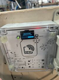
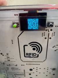
| − | PoE node voor the [[Metal | + | PoE node voor the [[Metal Mitresaw / Afkortzaag Metaal|Metal Mitre saw]] based on a [[PowerNode White]]. The QR code points to [[https://wiki.makerspaceleiden.nl/mediawiki/index.php/QR_metalmitresaw this]] page. |
==Use== | ==Use== | ||
| Regel 22: | Regel 21: | ||
One of the 3-phase wires is routed through a current coil (directly; rather than through the connector; as there may be a fair but of current running through it). The opto couplers are wired to the pump and to the safety interlock. | One of the 3-phase wires is routed through a current coil (directly; rather than through the connector; as there may be a fair but of current running through it). The opto couplers are wired to the pump and to the safety interlock. | ||
| + | The software can be found in ACNode its examples (in the Arduino IDE) or on [https://github.com/MakerSpaceLeiden/AccesSystem/blob/master/lib-arduino/ACNode/examples GitHub]. | ||
| + | |||
| + | Werkt samen met de SafetyContactor; dus aan en uit zetten met de normale rode/groene knoppen. | ||
| + | |||
| + | |||
| + | =Checklist node= | ||
| + | |||
| + | Doel checken is | ||
| + | |||
| + | # Machine mag niet anders aan gaan dan met de zwarte draai schakelaar die actief van off naar on gezet wordt. Dus ze gaat enkel aan als de schakelaar beroerd wordt. Dan en alleen dan. Dus ze mag nooit spontaan aan gaan; dus niet na power cycle node, niet na terugkomen spanning na een spanningsonderbreking of bij bewust aanzetten met groene knop terwijl de zware knop in de 'on' staat. | ||
| + | # Machine moet 30 seconden na rode knop weer in-lock gaan/veilig gaan | ||
| + | # Powercycle van de node moet geen rare situaties opleveren | ||
| + | # Spanningsonderbreking 400 volt moet machine in veilige stand brengen. | ||
| + | # Timeout na 45 minuten moet de machine ook in veilige stand brengen. | ||
| + | # Machine mag nooit uit (of aan) gaan zonder gebruikers actie. Dus node/netwerk/etc verlies of een timeout mag niet leiden tot uitgaan of aangaan van de motor. | ||
| + | |||
| + | Stappen: | ||
| + | |||
| + | # Powercycle de node. Komt die terug op het netwerk ? | ||
| + | # Na powercycle; werkt de groene groene knop niet ? | ||
| + | # Zet de machine in de aan stand; swipe valid pas en controleer dat de machine niet AAN mag/kan/gaat met de groene knop. | ||
| + | # Zet de machine in de uit stand; swipe valid pas en controleer dat de machine AAN mag. | ||
| + | # Zet de machine uit met rode knop tijdens niet draaien.Check dat pas nodig is na 10-30 seconden om machine weer aan te zetten -EN- de groene knop eerst ingedrukt moet worden. | ||
| + | # Zet de machine uit met rode knop tijdens wel draaien. Check dat pas nodig is na 10-30 seconden om machine weer aan te zetten -EN- de groene knop eerst ingedrukt moet worden. | ||
| + | # Swipe; zet aan met groene knop; power cycle node; controleer dat de machine nog aan kan. | ||
| + | # Idem - maar dan met power cycle node tijdens draaien machine. | ||
| + | # Swipe; en check dat na XX minuten er een not-used timeout de zaak uit zet. | ||
| + | # Check dat de timeout niet activeert als de motor draait (eventueel met speciale firmware met korte timeout). | ||
| + | # Swipe, check dat de machine werkt. Zet hem uit. Onderbreek krachtstroom > 1 seconde en controleer dat de machine weer in de veilige stand staat. | ||
| + | |||
| + | =Electronics= | ||
| + | |||
| + | De node is gebaseerd op de 2023 [[PowerNode_White]] boards. | ||
| + | |||
| + | * Opto coupler om te kijken of de schakelaar in de 'aan' stand staat. | ||
| + | * Opto coupler om te kijken of de pompt loopt. | ||
| + | * Relay dat het interlock keten onderbreekt (6V, één NO contact) | ||
| + | * CurrentCoil om te zien dat de machine aan/uit is. | ||
| + | * No ethernet connector soldered on (and RTL8201 chip soldering has never been checked) | ||
| + | * 5V of AC/DC PSU used for both V5 and VPOE/switching of the 6volt relay | ||
| + | |||
| + | Unit is powered down when the welding area is powered down. | ||
| + | |||
| + | ==solder jumpers / config== | ||
| + | |||
| + | # Er wordt gebruik gemaakt van een 5 volt trafo. | ||
| + | ## Vint is cross soldered | ||
| + | ## POE is disabled | ||
| + | ## Vint wordt voor 5volt en voor 5 power gebruikt. | ||
| + | # De N van de 5 volt travo is ook de basis voor de opto couplers. | ||
| + | ## De N jumpers van de opto couplers zijn dus doorverbonden. | ||
| + | |||
| + | = Source code = | ||
| − | + | [https://github.com/MakerSpaceLeiden/AccesSystem https://github.com/MakerSpaceLeiden/AccesSystem] | |
==Board jumpers and settings== | ==Board jumpers and settings== | ||
| Regel 115: | Regel 167: | ||
=Electrics= | =Electrics= | ||
| − | Basically a [[ | + | Basically a [[Safety Relay]] combined with a hand/off/auto setting for the pump. A [[Node Metal Mitre Saw]] is being build (it is a 3-phase/krachtstroom machine) and will be placed in the safety interlock chain that keeps the relay powered. |
Huidige versie van 17 nov 2024 om 00:15
PoE node voor the Metal Mitre saw based on a PowerNode White. The QR code points to [this] page.
Inhoud
[verbergen]Use
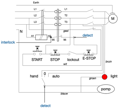
Swipe your card; this will unlock the 'red' button on the safety contractor to the left. Note that the unit will refuse to power on if the on/off button on the saw is in the unsafe, ON, position.
Once you are done - switch off the saw and then press the green button on the safety contractor to disable it. The unit will lock shortly thereafter.
Trouble shooting
See PowerNode White for details; or use the MENU button to see a QR code with logging.
The log file is available on http://192.168.6.144/. One can also telnet to this address. Logs are also sent to MQTT and to Syslog at the firewall. Or connect a serial cable; but be sure to use a Galvanic USB isolator.
Configuration
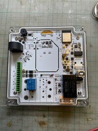
The unit contains a AC fed PowerNode White that is on WiFi. This is done by a 5Volt AC/DC convertor on the board (the back thing in the bottom right). It has a single relay that simply turns one of the phases (L) on and off.
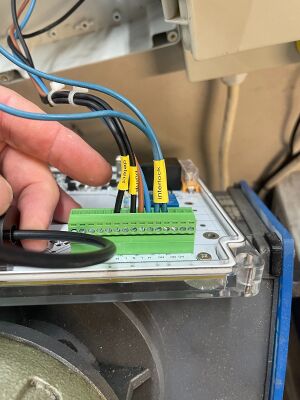
One of the 3-phase wires is routed through a current coil (directly; rather than through the connector; as there may be a fair but of current running through it). The opto couplers are wired to the pump and to the safety interlock.
The software can be found in ACNode its examples (in the Arduino IDE) or on GitHub.
Werkt samen met de SafetyContactor; dus aan en uit zetten met de normale rode/groene knoppen.
Checklist node
Doel checken is
- Machine mag niet anders aan gaan dan met de zwarte draai schakelaar die actief van off naar on gezet wordt. Dus ze gaat enkel aan als de schakelaar beroerd wordt. Dan en alleen dan. Dus ze mag nooit spontaan aan gaan; dus niet na power cycle node, niet na terugkomen spanning na een spanningsonderbreking of bij bewust aanzetten met groene knop terwijl de zware knop in de 'on' staat.
- Machine moet 30 seconden na rode knop weer in-lock gaan/veilig gaan
- Powercycle van de node moet geen rare situaties opleveren
- Spanningsonderbreking 400 volt moet machine in veilige stand brengen.
- Timeout na 45 minuten moet de machine ook in veilige stand brengen.
- Machine mag nooit uit (of aan) gaan zonder gebruikers actie. Dus node/netwerk/etc verlies of een timeout mag niet leiden tot uitgaan of aangaan van de motor.
Stappen:
- Powercycle de node. Komt die terug op het netwerk ?
- Na powercycle; werkt de groene groene knop niet ?
- Zet de machine in de aan stand; swipe valid pas en controleer dat de machine niet AAN mag/kan/gaat met de groene knop.
- Zet de machine in de uit stand; swipe valid pas en controleer dat de machine AAN mag.
- Zet de machine uit met rode knop tijdens niet draaien.Check dat pas nodig is na 10-30 seconden om machine weer aan te zetten -EN- de groene knop eerst ingedrukt moet worden.
- Zet de machine uit met rode knop tijdens wel draaien. Check dat pas nodig is na 10-30 seconden om machine weer aan te zetten -EN- de groene knop eerst ingedrukt moet worden.
- Swipe; zet aan met groene knop; power cycle node; controleer dat de machine nog aan kan.
- Idem - maar dan met power cycle node tijdens draaien machine.
- Swipe; en check dat na XX minuten er een not-used timeout de zaak uit zet.
- Check dat de timeout niet activeert als de motor draait (eventueel met speciale firmware met korte timeout).
- Swipe, check dat de machine werkt. Zet hem uit. Onderbreek krachtstroom > 1 seconde en controleer dat de machine weer in de veilige stand staat.
Electronics
De node is gebaseerd op de 2023 PowerNode_White boards.
- Opto coupler om te kijken of de schakelaar in de 'aan' stand staat.
- Opto coupler om te kijken of de pompt loopt.
- Relay dat het interlock keten onderbreekt (6V, één NO contact)
- CurrentCoil om te zien dat de machine aan/uit is.
- No ethernet connector soldered on (and RTL8201 chip soldering has never been checked)
- 5V of AC/DC PSU used for both V5 and VPOE/switching of the 6volt relay
Unit is powered down when the welding area is powered down.
solder jumpers / config
- Er wordt gebruik gemaakt van een 5 volt trafo.
- Vint is cross soldered
- POE is disabled
- Vint wordt voor 5volt en voor 5 power gebruikt.
- De N van de 5 volt travo is ook de basis voor de opto couplers.
- De N jumpers van de opto couplers zijn dus doorverbonden.
Source code
https://github.com/MakerSpaceLeiden/AccesSystem
Board jumpers and settings
Board:
- Rework 1 - half of OPTO resistors replaced by jumpers; 2x68k left in place
- Current coil - 6k8 burden
- Relay 1: Normal 5v Songle relay
- AC/DC unit soldered in
- Fuse soldered in (250 mAmp, slow)
- One current coil soldered in
Jumpers:
- VPOE and VPOE5 both explicit on 'off'
- 5V power via VINT
- Vpower via VINT
- N-jumpers for the Optocouples to get the N from the inputs.
Green Connector
| PIN | Description | Use |
|---|---|---|
| 1 | CUR2 | NC |
| 2 | CUR2 | NC |
| 3 | CUR1 | NC - black wire of motor is looped directly |
| 4 | CUR1 | NC - black wire of motor is looped directly |
| 5 | OPTO 2 | NC -- N for voltage sense is wired via jumper to pin 10 at back of board |
| 6 | OPTO 2 | Voltage sense across relay (label 'DETECT') |
| 7 | OPTO 1 | NC -- N for voltage sense is wired via jumper to pin 10 at back of board |
| 8 | OPTO 1 | Pump sense (label 'PUMP') |
| 9 | L input | L AC in (brown) |
| 10 | N input | N AC in (blue) |
| 11 | Relay 1 NO | Interlock (blue) |
| 12 | Relay 1 Common | Interlock (blue) |
| 13 | Relay 2 NO | NC |
| 14 | Relay 2 NC | NC |
| 15 | Relay 2 common | NC |
The motor current goes directly through the coil; we're not making use of the connector. Reason for this is that we're not quite sure of the (starting) currents.
Electrics
Basically a Safety Relay combined with a hand/off/auto setting for the pump. A Node Metal Mitre Saw is being build (it is a 3-phase/krachtstroom machine) and will be placed in the safety interlock chain that keeps the relay powered.
Log
Mon 1 Jan 2024 20:21:02 CET ac/log/metalmitresaw {
"manual_poweroff": 0,
"idle_poweroff": 0,
"errors": 0,
"ota": true,
"node": "woodlathe",
"machine": "woodlathe",
"maxMqtt": 384,
"id": "887124a4ae30",
"ip": "192.168.6.144",
"net": "UTP",
"mac": "30:AE:A4:24:71:8B",
"beat": 1704136278,
"alive-uptime": 8399,
"approve": 1,
"deny": 0,
"requests": 1,
"cache_hit": 1,
"cache_miss": 0,
"cache_purge": 0,
"cache_update": 1,
"mqtt_reconnects": 1,
"loop_rate": 15.13943768,
"coreTemp": 53.33333333,
"heap_free": 168180,
"rfid_scans": 1,
"rfid_misses": 131133,
"rfid": "RFID-MFRC522",
"state": "Waiting for card, screen dark",
"seconds_in_state": [
0,
3,
0,
0,
0,
1244,
0,
0,
0,
7445,
0,
2,
3,
0
],
"normal_poweroff": 1,
"fw": "/Users/dirkx/Documents/Arduino/AccesSystem/lib-arduino/ACNode/examples/WoodLatheNode/WoodLatheNode.ino Jan 1 2024 17:45:18"
}
History
Latest incarnation installed late 2023.
