Node DeWalt: verschil tussen versies
| (9 tussenliggende versies door 4 gebruikers niet weergegeven) | |||
| Regel 1: | Regel 1: | ||
| − | [[Category: | + | [[Category:Nodes & network devices]] |
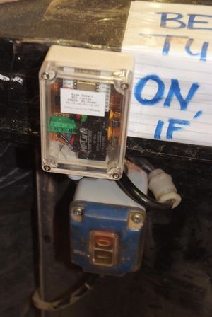
| + | [[Bestand:Dewalt-mounted.jpg|miniatuur|DeWalt machine on off]] | ||
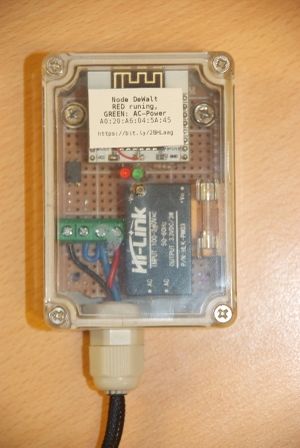
| + | [[Bestand:Dewalt-outside.jpg|miniatuur|DeWalt node/verklikker]] | ||
| − | Kleine ESP6822 node die monitored of een machine aangelaten/gebruikt wordt. Deze specifieke iteratie zit op de [[ | + | Kleine ESP6822 node die monitored of een machine aangelaten/gebruikt wordt. Deze specifieke iteratie zit op de [[DeWalt Wood Chip Extractor / Grote afzuiger|DeWalt Grote Afzuiger]] - en rapporteert of het ding in het stopcontact zit en of ze aan staat/draait. |
Planning is om ze op de compressors en afzuigers te hebben (en andere dingen die vaak aangelaten worden). | Planning is om ze op de compressors en afzuigers te hebben (en andere dingen die vaak aangelaten worden). | ||
| − | The unit is nearly identical to the [[ | + | The unit is nearly identical to the [[Node Compressor]]. |
| − | = Wiring and technical data = | + | =Wiring and technical data= |
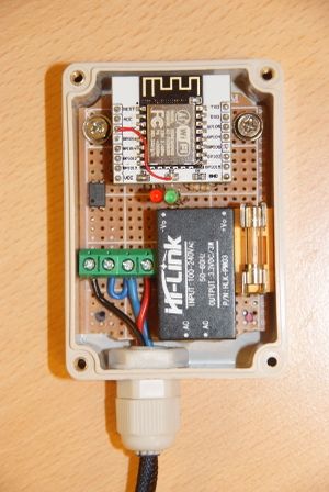
[[Bestand:Dewalt-inside.jpg|miniatuur|DeWalt node/verklikker - wiring]] | [[Bestand:Dewalt-inside.jpg|miniatuur|DeWalt node/verklikker - wiring]] | ||
| Regel 16: | Regel 18: | ||
Both expect AC/230 volt. The green LED is wired directly to the PSU. The blue LED has the same role as the Aart led in the other nodes. And the Red LED is swiched in software and should follow voltage detect on the Optocoupler input. | Both expect AC/230 volt. The green LED is wired directly to the PSU. The blue LED has the same role as the Aart led in the other nodes. And the Red LED is swiched in software and should follow voltage detect on the Optocoupler input. | ||
| − | Code in | + | Code in [https://github.com/dirkx/AccesSystem/blob/master/lib-arduino/ACNode/examples/DeWaltNode/DeWaltNode.ino github<span class="mw_htmlentity"></span>]. |
The 3v3 on the duaghter board is wired to the ADC -- so the PSU can power the board through this pin. The VCC pin runs via an 5v->3v3 regulator on the back. This lets us re-program it (e.g. when OTA has failed) with a standard ESP 5v programming board (such as any|Witty Cloud ESP12 or similar board (Around 3 euro for a programmer and an ESP12E). | The 3v3 on the duaghter board is wired to the ADC -- so the PSU can power the board through this pin. The VCC pin runs via an 5v->3v3 regulator on the back. This lets us re-program it (e.g. when OTA has failed) with a standard ESP 5v programming board (such as any|Witty Cloud ESP12 or similar board (Around 3 euro for a programmer and an ESP12E). | ||
| Regel 22: | Regel 24: | ||
Current mac address is '''A0:20:A6:04:5A:45''' -- the node is on wifi, so no switch port assigned. It flags as 'ESP_045A45' as its DHCP client name. | Current mac address is '''A0:20:A6:04:5A:45''' -- the node is on wifi, so no switch port assigned. It flags as 'ESP_045A45' as its DHCP client name. | ||
| − | = Opto electronics = | + | =Opto electronics= |
| − | |||
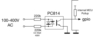
[[Bestand:Opto-wiring.png|400px|Wiring of the 3 opto couplers]] | [[Bestand:Opto-wiring.png|400px|Wiring of the 3 opto couplers]] | ||
| − | = Typical log = | + | =Typical log= |
| − | |||
{ | { | ||
"node": "dewalt", | "node": "dewalt", | ||
Versie van 16 nov 2024 om 23:16
Kleine ESP6822 node die monitored of een machine aangelaten/gebruikt wordt. Deze specifieke iteratie zit op de DeWalt Grote Afzuiger - en rapporteert of het ding in het stopcontact zit en of ze aan staat/draait.
Planning is om ze op de compressors en afzuigers te hebben (en andere dingen die vaak aangelaten worden).
The unit is nearly identical to the Node Compressor.
Wiring and technical data
The 4 screw terminals are AC (2x) and Optocoupler detect (2x). AC is nearest to the PSU; the inputs are 'under' the opto-coupler wires (the resistors are on the back of the board).
The fuse is a 800 mA fast (it should probably be a 50 or 100 mA slow).
Both expect AC/230 volt. The green LED is wired directly to the PSU. The blue LED has the same role as the Aart led in the other nodes. And the Red LED is swiched in software and should follow voltage detect on the Optocoupler input.
Code in github.
The 3v3 on the duaghter board is wired to the ADC -- so the PSU can power the board through this pin. The VCC pin runs via an 5v->3v3 regulator on the back. This lets us re-program it (e.g. when OTA has failed) with a standard ESP 5v programming board (such as any|Witty Cloud ESP12 or similar board (Around 3 euro for a programmer and an ESP12E).
Current mac address is A0:20:A6:04:5A:45 -- the node is on wifi, so no switch port assigned. It flags as 'ESP_045A45' as its DHCP client name.
Opto electronics
Typical log
  {
     "node": "dewalt",
     "machine": "dewalt",
     "maxMqtt": 1258,
     "id": "285253",
     "ip": "192.168.6.211",
     "net": "WiFi",
     "mac": "A0:20:A6:04:5A:45",
     "beat": 0,
     "approve": 0,
     "deny": 0,
     "requests": 0,
     "mqtt_reconnects": 2,
     "loop_rate": 22560.2,
     "heap_free": 27104,
     "state": "Powered - but idle",
     "powered_time": 271192,
     "running_time": 157,
     "ota": true,
     "acstate": true
  }


