Slicing a 3D object to SVG: verschil tussen versies
k (→Example with an STL: typo) |
|||
| (6 tussenliggende versies door 4 gebruikers niet weergegeven) | |||
| Regel 1: | Regel 1: | ||
| + | [[Category:Tutorials]][[Category:3D printing tools]] | ||
One can use OpenSCAD to slice a 3D STL or an object made in OpenSCAD into SVG usable with the Lasersaur. | One can use OpenSCAD to slice a 3D STL or an object made in OpenSCAD into SVG usable with the Lasersaur. | ||
| Regel 8: | Regel 9: | ||
The typical workflow is | The typical workflow is | ||
| − | # | + | # Create an OpenSCAD object, or import an STL of an object into OpenScad |
| − | # Add the | + | # Add the slicing code below |
| − | # Adjust the | + | # Adjust the parameters |
# Render the object | # Render the object | ||
| − | # Save the resulting SVG | + | # Save the resulting object as SVG |
| − | # Open | + | # Open the SVG in Inkscape to check and perhaps make it a bit more efficient by moving things around and/or nesting things |
| − | # Export/upload the SVG from | + | # Export/upload the SVG from Inkscape to the Lasersaur |
== Example of a CSG object == | == Example of a CSG object == | ||
| Regel 45: | Regel 46: | ||
z_min = 0; // smallest z-coordinate object | z_min = 0; // smallest z-coordinate object | ||
| − | z_max = 23; // biggest z-coordinate object | + | z_max = 23; // biggest z-coordinate object (add 1 to be safe) |
slice = 1; // desired distance between cuts | slice = 1; // desired distance between cuts | ||
| Regel 60: | Regel 61: | ||
x = x_dist * (s % rowlength); // calculate coordinates per cut | x = x_dist * (s % rowlength); // calculate coordinates per cut | ||
y = y_dist * floor(s / rowlength); | y = y_dist * floor(s / rowlength); | ||
| − | z = z_min + s * slice; // calculate height | + | z = z_min + s * slice; // calculate height at which the cut should be made |
| − | translate(explode ? [-x, -y, z * 2] : [0, 0, 0]) // translation | + | translate(explode ? [-x, -y, z * 2] : [0, 0, 0]) // translation if explode==true |
| − | + | projection(cut = true) // actual cut | |
| − | + | translate([x, y, -z]) // -z gets the correct layer, x and y do the grid move | |
| − | + | thing(); | |
} | } | ||
</pre> | </pre> | ||
Huidige versie van 17 nov 2024 om 00:52
One can use OpenSCAD to slice a 3D STL or an object made in OpenSCAD into SVG usable with the Lasersaur.
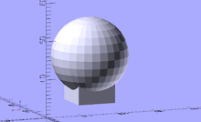
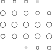
Or in other words, turning
 into
into  .
.
Needed: http://www.openscad.org/ - OpenScad (free).
The typical workflow is
- Create an OpenSCAD object, or import an STL of an object into OpenScad
- Add the slicing code below
- Adjust the parameters
- Render the object
- Save the resulting object as SVG
- Open the SVG in Inkscape to check and perhaps make it a bit more efficient by moving things around and/or nesting things
- Export/upload the SVG from Inkscape to the Lasersaur
Example of a CSG object
Below is an example of a hollow sphere on top of a hollow cube (thing() in below code) which is sliced; and each slice is then laid out flat.
$fn = 30; // setting the resolution to high values can seriously increase rendering time!

module thing() // a random object, in this case a hollow sphere on top of a hollow cube.
{
    difference()
    {
        union()
        {
            translate([0, 0, 5 ]) cube(10,true);
            translate([0, 0, 12]) sphere(d=20);
        }
        union()
        {
            translate([0, 0, 5 ]) cube(8,true);
            translate([0, 0, 12]) sphere(d=18);
        }
    }
}

// change these (measurements all in mm) -------------------------------------------------------------
x_dist      = 21; // desired horizontal distance between centre lines of projected cuts
y_dist      = 20; // desired vertical distance between centre lines of projected cuts

z_min       = 0;  // smallest z-coordinate object
z_max       = 23; // biggest z-coordinate object (add 1 to be safe)
slice       = 1;  // desired distance between cuts

explode     = false; // not in mm. false does nothing, x_dist and y_dist don't matter if this is true
// stop changing here --------------------------------------------------------------------------------

// some useful numbers
slicecount = (z_max - z_min)/slice; // this be the number of slices you get
rowlength  = floor(sqrt(slicecount)) + 1; // make rows and columns of projected cuts of equal length

// business end
for(s = [0:slicecount])
{
    x = x_dist * (s % rowlength); // calculate coordinates per cut
    y = y_dist * floor(s / rowlength);
    z = z_min + s * slice; // calculate height at which the cut should be made

    translate(explode ? [-x, -y, z * 2] : [0, 0, 0]) // translation if explode==true
        projection(cut = true)        // actual cut
            translate([x, y, -z])     // -z gets the correct layer, x and y do the grid move
                thing();
}
Example with an STL
An example of an STL that is loaded from a file and then sliced. You will have to manually adjust the Z range & slice distance.
 // 30x150x20 bbx
 import("dino.stl", convexity=3);

 z_min = 0;
 z_max = 30;
 x_max = 20;
 y_max = 150;
 slice = 0.5;

 n = floor(sqrt((z_max - z_min)/slice)+1);
 for(z = [-z_max:slice:z_min]) {
   i = (z + z_max) / slice;
   x = x_max * (i % n);
   y = Y_max * floor(i / n);
   translate([x,y,0]) {
       projection(cut=true)
           translate([0,0,z]) thing();
   };
 };