PowerNodeBlue-bringup: verschil tussen versies
(→Initial Bringup / checkout) |
(→Initial Bringup / checkout) |
||
| Regel 6: | Regel 6: | ||
== Initial Bringup / checkout == | == Initial Bringup / checkout == | ||
| − | Board 001: | + | Board 001 (selected as sacrificial): |
| − | # | + | |
| + | # Optically checked soldering/board as is | ||
# Plug in USB-C | # Plug in USB-C | ||
| − | ## Check 3v3 and 5v power; check red LED | + | ## Check 3v3 and 5v power; check red LED comes one. |
| − | ## check detection driver | + | ## Check for magic smoke/things getting hot (nothing should) |
| + | ## check detection of serial port/driver. It won't have any output at this point | ||
# PoE powering | # PoE powering | ||
## Place solder bridges Vpwr, V5 to VPOE/VPOE5 in Source field | ## Place solder bridges Vpwr, V5 to VPOE/VPOE5 in Source field | ||
| Regel 22: | Regel 24: | ||
# PoE and ESP32 | # PoE and ESP32 | ||
## Remove from USB; plug into PoE and check LEDs start flashing as soon as the power LED comes on. | ## Remove from USB; plug into PoE and check LEDs start flashing as soon as the power LED comes on. | ||
| + | |||
| + | From this point on - use a [[Galvanic USB isolator]] when connecting to the board with Ethernet plugged in. | ||
== Improvements == | == Improvements == | ||
# Add the word 'OFF' to the labels of all bridges in the PoE field (and not just the top one) | # Add the word 'OFF' to the labels of all bridges in the PoE field (and not just the top one) | ||
Versie van 4 feb 2025 om 16:04
15 units; 25/01/23 fab date.


Initial Bringup / checkout
Board 001 (selected as sacrificial):
- Optically checked soldering/board as is
- Plug in USB-C
- Check 3v3 and 5v power; check red LED comes one.
- Check for magic smoke/things getting hot (nothing should)
- check detection of serial port/driver. It won't have any output at this point
- PoE powering
- Place solder bridges Vpwr, V5 to VPOE/VPOE5 in Source field
- Do not place the Vpwr/5V bridges in the PoE field - these should be better labeled: e.g. have an 'OFF' text added to them like the one just above.
- Plug in PoE ethernet; check voltages: 5V, 3v3 and Vpwr==5V
- ESP32
- Solder in the ESP32
- Unplug PoE ethernet; plug in USB;
- Check 115200 baud visibility of ESP32 (press reset if needed). Should see
ets Jul 29 2019 12:21:46 ... rst:0x1 (POWERON_RESET),boot:0x13 (SPI_FAST_FLASH_BOOT)
- Check upload with default Arduino example `Blink' app against LEDs set to OUT1/OUT2 (GPIO 16, GPIO4) with ESP32 -> ESP32-WROOM-DA module with settings
 and
and 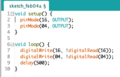 .
.
- PoE and ESP32
- Remove from USB; plug into PoE and check LEDs start flashing as soon as the power LED comes on.


From this point on - use a Galvanic USB isolator when connecting to the board with Ethernet plugged in.
Improvements
- Add the word 'OFF' to the labels of all bridges in the PoE field (and not just the top one)