Node Tussendeur: verschil tussen versies
Geen bewerkingssamenvatting |
|||
| (66 tussenliggende versies door dezelfde gebruiker niet weergegeven) | |||
| Regel 1: | Regel 1: | ||
[[Category:Nodes & network devices]] | [[Category:Nodes & network devices]][[Category:WhiteNode]] | ||
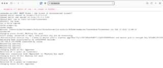
[[Bestand:TussendeurNode-log.png|320px]] | [[Bestand:TussendeurNode-log.png|320px]] | ||
{| class="wikitable" | {| class="wikitable" | ||
|- | |- | ||
| | | Troubleshooting || | ||
* If you are in the hallway | |||
** Check the display - use the right button to browse through the screens. | |||
* If you have physical access to the PCB: | |||
** Connect over USB; serial 8N1, 115200 -- using an battery powered laptop. Or, if powered; you must use a [[Galvanic USB isolator]]! | |||
* If you are on the LAN or WiFi of the space (direct or via an SSH tunnel): | |||
** [[telnet://192.168.6.160 telnet]] to 192.168.6.160, | |||
** Connnect over [[http://192.168.6.160 http]] with your web browser | |||
* Otherwise your options are: | |||
** Listen to [[mqtt:///#ac/log/tussendeur mqtt] - topic #ac/log (tussendeur) | |||
** Tail the syslog on the space local server after logging in over the VPN/SSH. | |||
|- | |- | ||
| | | IP address || 192.168.6.160 (LAN, PoE powered) | ||
|- | |||
| Hardware ethernet || 08:D1:F9:90:B3:63 (wired) See the [[Network setup overview]] if you want to power cycle it. | |||
|- | |- | ||
|} | |} | ||
= Normal operation = | = Normal operation = | ||
| Regel 31: | Regel 29: | ||
= Bypassing the node = | = Bypassing the node = | ||
[[Bestand:Bypass-dipaswitch.jpg|miniatuur|Bypass dip switch]] | [[Bestand:Bypass-dipaswitch.jpg|miniatuur|Bypass dip switch]] | ||
With the explicit permission from a trustee - a node can be bypassed. For example when it is broken. | With the explicit permission from a trustee - a node can be bypassed. For example when it is broken. There is a red dip switch on the back of the board; near the AC/DC transformer and the fuse. | ||
There is a red dip switch on the back of the board; near the AC/DC transformer and the fuse. | |||
Placing it in the ''''on' position''' will bypass the node (i.e. to the left in the picture); and provided power to the | Placing it in the ''''on' position''' will bypass the node (i.e. to the left in the picture); and provided power to the solenoid. | ||
Obviously - doing so without the express permission is a sure way to loose your membership. | Obviously - doing so without the express permission is a sure way to loose your membership. | ||
| Regel 74: | Regel 68: | ||
= Resetting the Node = | = Resetting the Node = | ||
Unplug the ethernet cable in the main patch cabinet. | Unplug the ethernet cable in the main patch cabinet. See [[Network setup overview|this page for details]]. | ||
Wait | Wait at least 60 seconds until you try again (the ESP32 is quite slow & it needs to create some cryptographic date before it can start communicating over https/SSL). | ||
= Electronics = | = Electronics = | ||
De node is PoE powered; set to 12 Volt. | De node is PoE powered; set to 12 Volt. | ||
=== rfid scanner === | |||
The middle section is broken out and, with an 6 wire, RJ12 socketed (ISDN) wire, interconnected. | |||
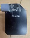
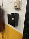
[[Bestand:Tussen-rfid-scanner-front.jpg|100px|kaderloos]][[Bestand:Tussen-rfid-scanner-back.jpg|100px|kaderloos]][[Bestand:Tussen-rfid-scanner-outside1.jpg|100px|kaderloos]][[Bestand:Tussen-rfid-scanner-outside2.jpg|100px|kaderloos]][[Bestand:Tussen-rfid-scanner-outside3.jpg|100px|kaderloos]] | |||
So the main PCB is inside; the RDID bit is outside. The wire carries i2c, 3v3 power and the 2 reset/IRQ signals. | |||
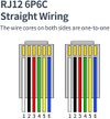
The wiring is straight; RJ12 wiring: | |||
[[Bestand:Rj12-straight.jpg|100px|RJ12 straight]] | |||
== Board jumpers and settings == | == Board jumpers and settings == | ||
[[Bestand:Nodetussendeur-jumpers-diode.jpg|miniatuur|Note diode and red/black wire to bring 12v to the solenoid, blusdiode over solenoid]] | |||
=== Board 5 === | === Board - Serial #5 === | ||
# Rework 1 - verwijderen ESD diodes antenne | # Rework 1 - verwijderen ESD diodes antenne | ||
# Rework 2 - omdraaien transistors programmering | # Rework 2 - omdraaien transistors programmering | ||
# 0-ohm (jumpering) R109 removed; 5V of USB not connected to 5V rail. | # 0-ohm (jumpering) R109 removed; 5V of USB not connected to 5V rail. | ||
# Fixed 5v resistor replaced by potentionmeter; and set to | # Fixed 5v resistor replaced by potentionmeter; and set to 7 (was12) Volt | ||
=== Jumpers: === | === Jumpers: === | ||
# Vpoe - Slow Start | # Vpoe - set to 'Slow Start' | ||
# Vpoe5 - Slow Start | # Vpoe5 - set 'Slow Start' | ||
# Vpwr - Vpoe as source | # Vpwr - set to 'Vpoe' as source. | ||
# 5V- Vpoe5 as source | # 5V- set to 'Vpoe5' as source. | ||
# Out2 - via AC jumpers | # Out2 - via the two AC jumpers | ||
=== Special Wiring === | === Special Wiring === | ||
The 12 volt DC of VPoe is wired to L/N of the normal 220V AC input. So that the C/NO of relay 2 is a simple 12 volt on/off. | The 12 volt DC of VPoe is wired to L/N of the normal 220V AC input. So that the C/NO of relay 2 is a simple 12 volt on/off. | ||
There is an extra diode wired across the coil-wires. | |||
== Connectors == | == Connectors == | ||
=== Green Connector === | === Green Connector === | ||
[[Bestand: | [[Bestand:nodetussendeur-connector.jpg|miniatuur|Node tussendeur, connector for solenoid at the bottom; note large capacitor]] | ||
Only the bottom 2 sockets are needed/switched - and can be wired 1:1 to the solenoid. | |||
{| class="wikitable" | {| class="wikitable" | ||
|- | |- | ||
| Regel 142: | Regel 150: | ||
| 15 || Relay 1 common || 12 volt from solenoid | | 15 || Relay 1 common || 12 volt from solenoid | ||
|} | |} | ||
== current and solenoid == | |||
Somehow the solenoids current increases at 12Volt to a point where it needs well over 30 watt. At which point the PoE switch current protection trips. | |||
Solved for now by reducing the voltage to about 7 volt. No trips observed since. | |||
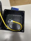
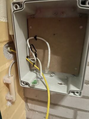
[[Bestand:Tussen-rfid-scanner-inside1.jpg|300px|kaderloos]] | |||
Gele draad RJ12/6 aderige kabel naar de buiten RFID scanner. Witte kabel met RJ45 stekker - ethernet; Grijze kabel met groene stekkertje - naar Solenoid. | |||
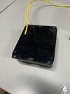
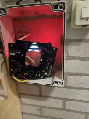
[[Bestand:Tussen-rfid-scanner-inside2.jpg|300px|kaderloos]] | |||
Zaak hangt nu in het kastje. | |||
= Source code = | = Source code = | ||
https://github.com/MakerSpaceLeiden/AccessSystem/lib-arduino/ACNode/examples/TussendeurNode | https://github.com/MakerSpaceLeiden/AccessSystem/lib-arduino/ACNode/examples/TussendeurNode | ||
Tag as pushed ```tussendeur-2024-12-01```` | |||
= Bill of material = | = Bill of material = | ||
| Regel 155: | Regel 179: | ||
| ESP32 || ~3.50 | | ESP32 || ~3.50 | ||
|- | |- | ||
| Big green Connector|| ~1.50€ | | <strike>Big green Connector</strike>|| <strike>~1.50€</strike> | ||
|- | |||
| Small green Connector|| ~0.20€ | |||
|- | |- | ||
| RJ45 connector || ~0.10 | | RJ45 connector || ~0.10 | ||
|- | |- | ||
| Solenoid 12V || ~39€ | | Solenoid 12V door || ~39€ | ||
|- | |- | ||
| OLED display || ~3.50€ | | OLED display || ~3.50€ | ||
|- | |- | ||
| Buttons x3 || ~0.30€ | | Buttons x3 || ~0.30€ | ||
|- | |||
| Buzzer x1 || ~0.50€ | |||
|- | |||
| Busdiode, 1N6303A x1 || ~0.05€ | |||
|- | |||
| RJ12 socket x 2 || ~1.00 | |||
|- | |||
| RJ12 plug x 2 || ~1.00 | |||
|- | |||
| Extra super big capacitor || free, donated to MSL | |||
|- | |- | ||
| 12v coil relay; switch 240ACV/3A || free, donated to MSL | | 12v coil relay; switch 240ACV/3A || free, donated to MSL | ||
|- | |- | ||
|} | |} | ||
= History = | = History = | ||
{| class="wikitable" | |||
Rebuild | |- | ||
! Datum / Date!! Description | |||
|- | |||
| 2016 || Rebuild | |||
|- | |||
| Early 2018 || upgradedwith the 1.1 batch (yellow boards) | |||
|- | |||
| 2022/2/19 || [[https://github.com/MakerSpaceLeiden/AccesSystem/releases/tag/cache-fix-2022-02-19-1.00 Firmware last updated]] - to fix caching and a range of errors found by Duco when using the Arduino rather than the VisualStudio setup. | |||
|- | |||
| 2024-12-01 || replaced by a the black variation of [[PowerNode White]] - software tag tussendeur-2024-12-01 | |||
|- | |||
| 2024-12-07 || Solenoid replaced by Alex; one spare bought. | |||
|- | |||
| 2024-01-?? || Voltage has gone to some mad high value. Reduced to sensible < 12 volt. Adjusting screw may need a blob of nail-polish to lock in place. | |||
|- | |||
|} | |||
Huidige versie van 6 feb 2025 21:31
| Troubleshooting |
|
| IP address | 192.168.6.160 (LAN, PoE powered) |
| Hardware ethernet | 08:D1:F9:90:B3:63 (wired) See the Network setup overview if you want to power cycle it. |
Normal operation
Swipe your card - node should beeb for 4 seconds; or give a short intermittent deny signal.
Bypassing the node
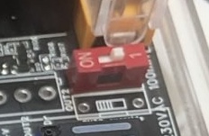
With the explicit permission from a trustee - a node can be bypassed. For example when it is broken. There is a red dip switch on the back of the board; near the AC/DC transformer and the fuse.
Placing it in the 'on' position will bypass the node (i.e. to the left in the picture); and provided power to the solenoid.
Obviously - doing so without the express permission is a sure way to loose your membership.
Trouble Shooting
Check what is on the display. The first QR code will bring you to this page. The second QR code will show you the logs in a browser. You can also telnet to the IP address shown in the 'MORE' display to see the log in real time.
See this page for more details.
Swipe ok - but does not want to open door
- Do you see waiting for card on the display ? If so - it has not read your card (yet).
- Did you hear one or more beebs when you swiped ? If so - your card is picked up ok ?
If you hear beebs:
- Did you hear 3 or more beeps when you swiped ? If so - your card is not getting permission from the system.
- Does your personal page in mijn.makerspaceleiden.nl show that you have permission ?
- Did you get your permissions quite recently ?
- Is the internet in the space up and running (as it only periodically updates its database).
The Machine does not want to accept my badge
- Do you hear a beeb when swiping ? If so - it has read your card -- and see above issues.
If it did not beeb:
- Did it work on the door ?
- Does it work on any other machine ?
If so - your badge is fine - but we may have a broken ACNode or a broken reader. Report this to the mailing list - or if you know a little of IT and electronics - go to the troubleshooting section and connect to the log via your webbrowser or via telnet. Then swipe again and see what really happens.
Note that we are, at this time, not sure if these nodes will survive the welding area.
Resetting the Node
Unplug the ethernet cable in the main patch cabinet. See this page for details.
Wait at least 60 seconds until you try again (the ESP32 is quite slow & it needs to create some cryptographic date before it can start communicating over https/SSL).
Electronics
De node is PoE powered; set to 12 Volt.
rfid scanner
The middle section is broken out and, with an 6 wire, RJ12 socketed (ISDN) wire, interconnected.
So the main PCB is inside; the RDID bit is outside. The wire carries i2c, 3v3 power and the 2 reset/IRQ signals.
The wiring is straight; RJ12 wiring:
Board jumpers and settings
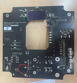
Board - Serial #5
- Rework 1 - verwijderen ESD diodes antenne
- Rework 2 - omdraaien transistors programmering
- 0-ohm (jumpering) R109 removed; 5V of USB not connected to 5V rail.
- Fixed 5v resistor replaced by potentionmeter; and set to 7 (was12) Volt
Jumpers:
- Vpoe - set to 'Slow Start'
- Vpoe5 - set 'Slow Start'
- Vpwr - set to 'Vpoe' as source.
- 5V- set to 'Vpoe5' as source.
- Out2 - via the two AC jumpers
Special Wiring
The 12 volt DC of VPoe is wired to L/N of the normal 220V AC input. So that the C/NO of relay 2 is a simple 12 volt on/off.
There is an extra diode wired across the coil-wires.
Connectors
Green Connector
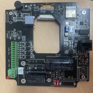
Only the bottom 2 sockets are needed/switched - and can be wired 1:1 to the solenoid.
| PIN | Description | Use |
|---|---|---|
| 1 | CUR2 | NC |
| 2 | CUR2 | NC |
| 3 | OPTO 4 | NC |
| 4 | OPTO 3 | NC |
| 5 | OPTO 2 | NC |
| 6 | OPTO 2 | NC |
| 7 | OPTO 1 | NC |
| 8 | OPTO 1 | NC |
| 9 | L input | L; 12 Volt out |
| 10 | N input | N; GND |
| 11 | Relay 1 NO | NC |
| 12 | Relay 1 Common | NC |
| 13 | Relay 1 NC | NA |
| 14 | Relay 1 NC | 12 volt to solenoid |
| 15 | Relay 1 common | 12 volt from solenoid |
current and solenoid
Somehow the solenoids current increases at 12Volt to a point where it needs well over 30 watt. At which point the PoE switch current protection trips.
Solved for now by reducing the voltage to about 7 volt. No trips observed since.
Gele draad RJ12/6 aderige kabel naar de buiten RFID scanner. Witte kabel met RJ45 stekker - ethernet; Grijze kabel met groene stekkertje - naar Solenoid.
Zaak hangt nu in het kastje.
Source code
https://github.com/MakerSpaceLeiden/AccessSystem/lib-arduino/ACNode/examples/TussendeurNode
Tag as pushed ```tussendeur-2024-12-01````
Bill of material
| Back v1.11 node board | ~35 |
| ESP32 | ~3.50 |
| Small green Connector | ~0.20€ |
| RJ45 connector | ~0.10 |
| Solenoid 12V door | ~39€ |
| OLED display | ~3.50€ |
| Buttons x3 | ~0.30€ |
| Buzzer x1 | ~0.50€ |
| Busdiode, 1N6303A x1 | ~0.05€ |
| RJ12 socket x 2 | ~1.00 |
| RJ12 plug x 2 | ~1.00 |
| Extra super big capacitor | free, donated to MSL |
| 12v coil relay; switch 240ACV/3A | free, donated to MSL |
History
| Datum / Date | Description |
|---|---|
| 2016 | Rebuild |
| Early 2018 | upgradedwith the 1.1 batch (yellow boards) |
| 2022/2/19 | [Firmware last updated] - to fix caching and a range of errors found by Duco when using the Arduino rather than the VisualStudio setup. |
| 2024-12-01 | replaced by a the black variation of PowerNode White - software tag tussendeur-2024-12-01 |
| 2024-12-07 | Solenoid replaced by Alex; one spare bought. |
| 2024-01-?? | Voltage has gone to some mad high value. Reduced to sensible < 12 volt. Adjusting screw may need a blob of nail-polish to lock in place. |
