Node Lights Out: verschil tussen versies
(→Building wiring) |
(→Update September 2019) |
||
| Regel 21: | Regel 21: | ||
White is the gnd, the colours (brown, orange, green) are the signal wires. | White is the gnd, the colours (brown, orange, green) are the signal wires. | ||
| − | Furthermore GPIO 5 has been wired to a 433 Mhz receiver - for [[MainsSensor|our radio based mains-monitoring]]. As the digital out is 5volt - there is a simple 3k3/1k8 voltage divider to bring the signal to the 3v3 that the ESPs GPIO likes. | + | Furthermore GPIO 34 (was 5) has been wired to a 433 Mhz receiver - for [[MainsSensor|our radio based mains-monitoring]]. As the digital out is 5volt - there is a simple 3k3/1k8 voltage divider to bring the signal to the 3v3 that the ESPs GPIO likes. |
= Building wiring = | = Building wiring = | ||
Versie van 9 sep 2019 om 21:39
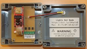
[OLIMEX PoE] gebaseerde node die kijkt naar de 3 AC netten van het licht.
Inhoud
[verbergen]Wiring and technical data
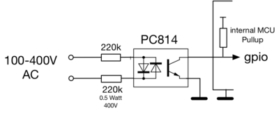
The 6 screw terminals are Optocoupler detect (2x3) of AC.
All 3 expect AC/230 volt. The RED led on the front is the 'AartLED'.
Code in [[1]]/
Current mac address is 3C:71:BF:10:62:A7 -- wired to the top patch panel, port 23. It is currently connected by a yellow cable to the top switch; port 23 (auto-negotiation, no further settings)
Update September 2019
The AC voltage resistors/optocouplers have been moved out of the low voltage electronics box; and now reside in/behind the two light switches. With just 2 and 4 wires (gnd/E and signal/C of the optocouplers) going to the grey box.
White is the gnd, the colours (brown, orange, green) are the signal wires.
Furthermore GPIO 34 (was 5) has been wired to a 433 Mhz receiver - for our radio based mains-monitoring. As the digital out is 5volt - there is a simple 3k3/1k8 voltage divider to bring the signal to the 3v3 that the ESPs GPIO likes.
Building wiring
Note that the building wiring is a bit funny - an earth wire is used as a black-switch phase wire in the leftmost switch. Talk first to the trustees if you want to fix it - as this is a key part of building relative to the agreements made with the landlord.
Opto electronics
Typical log
AC1 to AC3 are the OPTO couplers state; True is off (there is a pull up at work), False is AC voltage detected.
    {
      "node": "lights",
      "machine": "lights",
      "maxMqtt": 768,
      "id": "a46210bf713c",
      "ip": "192.168.3.173",
      "net": "UTP",
      "mac": "3C:71:BF:10:62:A7",
      "beat": 0,
      "approve": 0,
      "deny": 0,
      "requests": 0,
      "cache_hit": 0,
      "cache_miss": 0,
      "mqtt_reconnects": 1,
      "loop_rate": 11137.78,
      "coreTemp": 72.22222,
      "heap_free": 223272,
      "state": "Powered - no lights",
      "powered_time": 1195,
      "running_time": 0,
      "ota": true,
      "acstate1": true,
      "acstate2": true,
      "acstate3": true
   }

