Project Radar Boards Schiphol Control: verschil tussen versies
(→Schiphol Airtraffic Control displays) |
k (→Schiphol Airtraffic Control displays) |
||
| Regel 19: | Regel 19: | ||
<tabs> | <tabs> | ||
<tab name="board 50219"> | <tab name="board 50219"> | ||
| − | {{Board 50219}} | + | {{:Board 50219}} |
</tab> | </tab> | ||
<tab name = "board 50.028"> | <tab name = "board 50.028"> | ||
Versie van 1 jul 2021 om 20:04
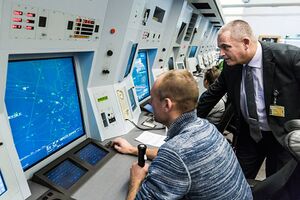
We got a [pile of Control Tower displays from Schiphol airport (or Eurocontrol, etc)] used for tracking what is in the air.
They are basically small 2-3 CPU boards on a common RS 485 bus or on RS 232. One CPU is purely for programming. The other is the main board and handles the traffic on the bus (it may be ASTERIX format?) and the other handles the display. They are interconnected by a TTL serial on 9600 8N1. Each box also contains a high quality PSU.
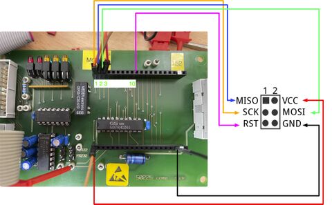
The programming chip is also 9600 8N1 and contains some debugging tooling. Photo below shows the testpoints used for programming.
But easiest may be to use normal ATMEL programmeing on MISO/MOSI - which are nicely broken out on the connector.
Inhoud
[verbergen]Code
Some fairly functional code: https://github.com/MakerSpaceLeiden/AirtrafficControlDisplaysSchiphol
Bestand:Schiphol-first-light.mov
grote (50229) display eerste test-tekst (youtube)
Schiphol Airtraffic Control displays
Om een van de hierboven ge-"transclude"d pagina's te wijzigen, bezoek de pagina via Categorie:DisplayBoardsSchiphol.
Datasheet displays
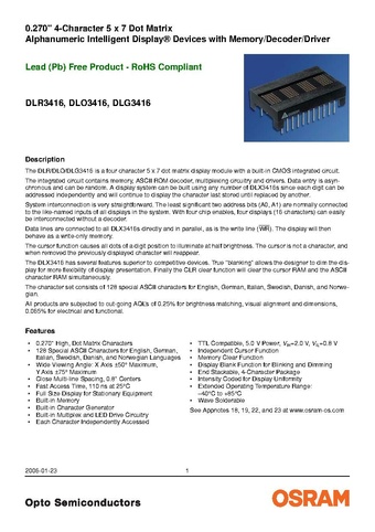
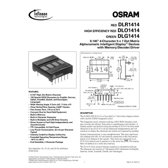
50228 and 50229 use PD44x (PD4435, red) displays. 50.028 and 50219 use DLO3416 (red). 50227 uses DLO1414 (smaller 4-digit display, red). 7003-assy uses PD2573 (green).
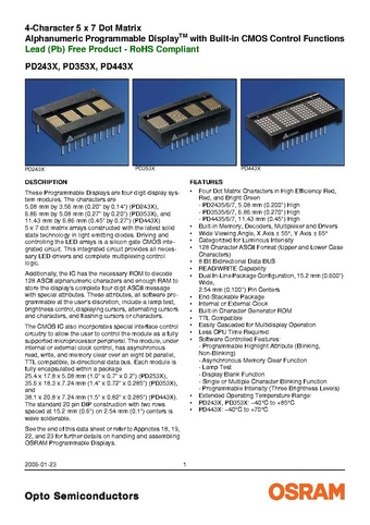 Code in https://github.com/MakerSpaceLeiden/AirtrafficControlDisplaysSchiphol/blob/main/shared/pd44.c
Various people hack them
- https://www.flickr.com/photos/okini393939/5148872258
- https://github.com/TiNredmc/PD443X_Lib
- https://github.com/TiNredmc/PD443Xclock
Main Board 50XXX series
Connection on the main bord - top row near the yellow 'TOP1' label. Shared by all 50XXX boards.
Wiring / pinout main CPU board
| TOP 1 | SCK of CPU display board |
| TOP 2 | MISO of CPU display board |
| TOP 3 | MOSI of CPU display board |
| TOP 10 | RST of CPU display board |
| TOP 13,14 | TX/RX of CPU display board |
| BOT far left/right | Power |
