Node Compressor: verschil tussen versies
| Regel 16: | Regel 16: | ||
The 3v3 on the duaghter board is wired to the ADC -- so the PSU can power the board through this pin. The VCC pin runs via an 5v->3v3 regulator on the back. This lets us re-program it (e.g. when OTA has failed) with a standard ESP 5v programming board (such as any|Witty Cloud ESP12 or similar board (Around 3 euro for a programmer and an ESP12E). | The 3v3 on the duaghter board is wired to the ADC -- so the PSU can power the board through this pin. The VCC pin runs via an 5v->3v3 regulator on the back. This lets us re-program it (e.g. when OTA has failed) with a standard ESP 5v programming board (such as any|Witty Cloud ESP12 or similar board (Around 3 euro for a programmer and an ESP12E). | ||
Current mac address is ''' | Current mac address is ''' A0:20:A6:07:93:F3''' / 192.168.6.217 (dhcp) | ||
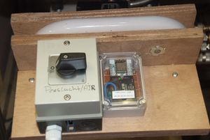
The AC sense wiring is across the pressure driven on-off switch. Rather than between the N and the L of the motor. The reason for this is a rather larger leak current which shows a 100V in the off position (and 230V when on) -- both sufficient to drive the optocoupler. So instead we have wired the optocoupler across the on-off switch. Sensing the leak voltage when the motor is off; and the no voltage (i.e. across the 0 ohm switch poles) when the switch is on and hence the motor on. | The AC sense wiring is across the pressure driven on-off switch. Rather than between the N and the L of the motor. The reason for this is a rather larger leak current which shows a 100V in the off position (and 230V when on) -- both sufficient to drive the optocoupler. So instead we have wired the optocoupler across the on-off switch. Sensing the leak voltage when the motor is off; and the no voltage (i.e. across the 0 ohm switch poles) when the switch is on and hence the motor on. | ||
Versie van 16 feb 2019 11:01


ESP6822 gebaseerde node die kijkt of the compressor (nog) aan staat. De 'sense' pin zit aan de 'druk' schakelaar van de compressor.
The node is nearly identical to the NodeDeWalt.
Wiring and technical data
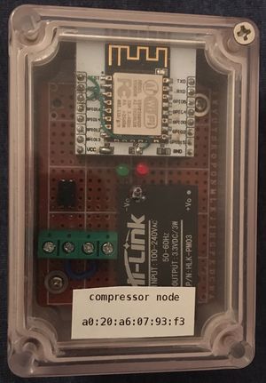
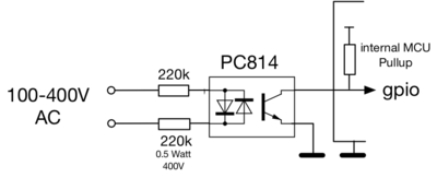
The 2 screw terminals are an Optocoupler for AC. It expects AC/230 volt. The RED led on the front is the 'AartLED'.
Code in [[1]]. Opto coupler is wired to GPIO 13, the red LED to GPIO 15 while the green LED sits across the 3v3 of the PSU.
The 3v3 on the duaghter board is wired to the ADC -- so the PSU can power the board through this pin. The VCC pin runs via an 5v->3v3 regulator on the back. This lets us re-program it (e.g. when OTA has failed) with a standard ESP 5v programming board (such as any|Witty Cloud ESP12 or similar board (Around 3 euro for a programmer and an ESP12E).
Current mac address is A0:20:A6:07:93:F3 / 192.168.6.217 (dhcp)
The AC sense wiring is across the pressure driven on-off switch. Rather than between the N and the L of the motor. The reason for this is a rather larger leak current which shows a 100V in the off position (and 230V when on) -- both sufficient to drive the optocoupler. So instead we have wired the optocoupler across the on-off switch. Sensing the leak voltage when the motor is off; and the no voltage (i.e. across the 0 ohm switch poles) when the switch is on and hence the motor on.
The software corrects for this by negating the check in line [| 169].
Opto electronics
Typical log
-- not yet in use --
