Node Spacedeur
PoE powered Node on Ethernet voor de deur van de space zelf.
Inhoud
[verbergen]Electronics
Todo: Add
Bestand:POESP 1.0.pdf
schematic / POESP pinout
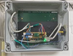
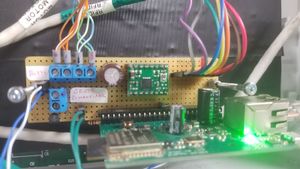
On the motherboard there are:
- resistor between "Set V++" and GND, setting the voltage output for the stepper motor ("Vmot" terminal of A4988) to 12V
- transistor for amplifying the pulses on GPIO16 for the buzzer
- pull-up resistor for MS1, ensuring the motor is making half-steps (?)
- R-C circuit for the a.k.a. "Grote Schakelaar"
- socket for A4988-type stepper motor driver
- 8-pin RFID reader connector (brown/red pin is rightmost)
- 4-screw terminal for the stepper motor
- 2-screw terminal for powering auxillary devices (not connected)
- 2-pin terminal for the buzzer, which sounds when RFID is read successfully
- 2-pin terminal for the a.k.a. "Grote Schakelaar". High when switch is off (or wire broken). Goes low when the switch is on.
The pinning on the RFID reader is (most probably):
| pin | function |
|---|---|
| 1 | SDA |
| 2 | SCK |
| 3 | MOSI |
| 4 | MISO |
| 5 | IRQ |
| 6 | GND |
| 7 | RESET |
| 8 | 3v3 |
Pinning ESP32
| ESP GPIO | functie |
|---|---|
| 2 | Stepper DIR |
| 4 | Stepper Enable |
| 5 | Stepper STEP |
| 16 | Buzzer |
| 34 | Grote Schakelaar |
| 13 | MOSI |
| 12 | MISO |
| 14 | SCK |
| 15 | SDA |
| 32 | RESET (optioneel) |
| 33 | IRQ (optioneel) |
Stepper schroef terminal
see labels on each wire, match with those on terminals
| Pin | functie |
|---|---|
| 1 | A - kleur onbekend |
| 2 | iA - kleur onbekend |
| 3 | B - kleur onbekend |
| 4 | iB - kleur onbekend |
Grote Schakelaar header
| Pin | functie |
|---|---|
| 1 | Deur sensor; pulled up; naar pin 34 van de ESP 32 |
| 2 | Digital ground |
2-screw terminal
| Pin | functie |
|---|---|
| 1 | 12Volt |
| 2 | power ground |

