Project Radar Boards Schiphol Control
Versie door DirkWillem (overleg | bijdragen) op 10 jun 2021 om 22:49
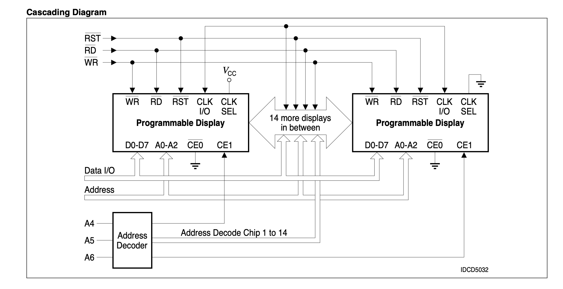
Seems to be the reference circuit from the display datasheet with an Atmel161:
Main connector
| 1 NC | 2 NC |
| 3 NC | 4 NC |
| 5 ? | 6 ? |
| 7 RST | 8 SCK |
| 9 MISO | 10 MOSI |
| 11 RX | 12 TX |
| 13 SS | 14 Vdd |
| 15 Vdd | 16 ? |
| 17 ? | GND |
| GND | GND |
Multiplexer
HC138 is een multiplexer (https://www.ti.com/lit/ds/symlink/sn74hc138.pdf?ts=1623312092250&ref_url=https%253A%252F%252Fwww.google.com%252F)
Pin 1,2,3 zijn de selects. 4,5 enables, G1 de active high
ATMEGA 161L
| 1 | MOSI - pin 9 connector |
| 2 | MISO - pin 10 connector |
| 3 | SCK - pin 8 connector |
| 4 | RST - pin 7 connector |
| 5 | RX - pin 11 connector |
| 6 | NC |
| 7 | TX - pin 12 connector |
| 8 | GND ? |
| 9 | GND ? |
| 10 | |
| 11 | |
| 12 | pin 10 display WR |
| 13 | pin 1 display RD |
| 14 | |
| 15 | |
| 16 | |
| 17 | |
| 18 | pin 9 display A0 |
| 19 | pin 8 display A1 |
| 20 | pin 7 display A2 |
| 21 | MCP 1 |
| 22 | MCP 2 |
| 23 | MCP 8 |
| 24 | pin 5 display CE1 |
| 25 | |
| 26 | pin 4 display RST |
| 27 | |
| 28 | |
| 29 | |
| 30 | pin 11 display D7 |
| 31 | pin 12 display D6 |
| 32 | pin 13 display D5 |
| 33 | pin 14 display D4 |
| 34 | pin 15 display D3 |
| 35 | pin 16 display D2 |
| 36 | pin 17 display D1 |
| 37 | pin 18 display D0 |
| 38 | VCC |
| 39 | |
| 40 | |
| 41 | |
| 42 | |
| 43 | |
| 44 | SS - pin 13 connector |
Display
https://nl.mouser.com/datasheet/2/311/00034150_0-1196251.pdf
