VK2000-build
Inhoud
[verbergen]Wiring
- N and single 220volt L via switch; black and blue
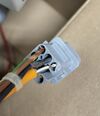
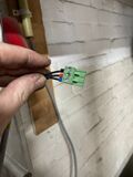
- 2x for the thermocouple - orange cable; white and brown
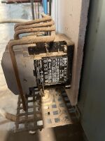
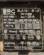
- 2x Normally open relays to switch a load contactor
- Earth wire
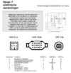
On a Harting HAN7Da connector.
RCD / Aardlekschakelaar
40A, 500mA residual current detector/aartlekschakelaar in de loop. It sits in the path to the 4+1 IEC wall socket.
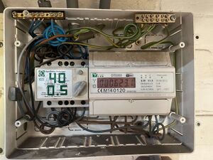
kWh meter
Dit is een DTS353 -- https://www.rdlmeters.com/product/dts353/ met een Wat-uur puls uitgang.
Deze is vermoedelijk low-voltage open collector. Plan is te beginnen met 3v3 volt en een 4.7 kΩ pull up resistor on the IO port of the node..
Sensor
- Nenniger GmbH, Berlin, Hochtemperatur S-Type Thermocouple
- Special type of cable for this (orange)
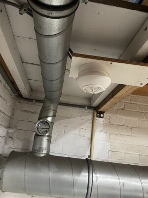
Hitte Sensor
een FIT-NP5R dry-relay (NO, NC) sokkel met een FITH-23010 hitte sensor.
Manuals as shipped
Actual manuals that were shipped with the unit (please keep)
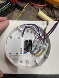
Wiring
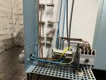
- Mains - 'tick' cable going to distribution panel
- L -- Phase 220v, Brown
- N -- Neutral, 220v, Blue
- Earth - terminated, Yellow
- Alert-signal, white -- not connected
- Dry relay - galvanically separate from mains - 'thin' cable going to oven control box
- Black - common
- Red - Normally open
- Blue - Normally closed
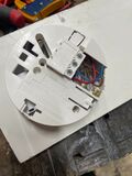
VK2000 Control signals
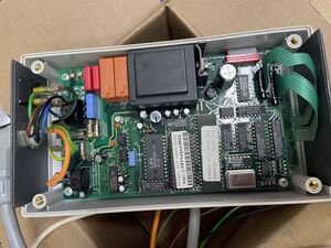
Our version has 2 relays; with an NO to the 'L'.
- Earth wire (yellow/green)
- Neutral wire (for the AC/DC) (blue)
- L wire (for AC/DC and as the feed of the relay outputs) (brown)
- Relay 1 out -- switching to L (black)
- Relay 2 out -- Switching to L (green)
- Purple wire - not connected
- Orange wire - white/brown - Pt
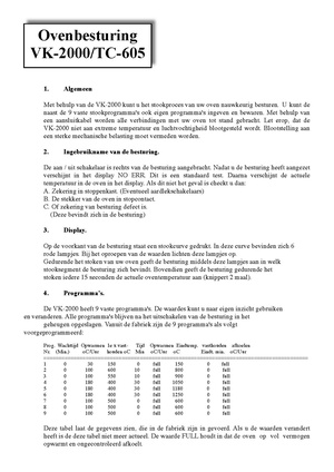
Manual
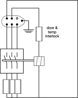
Wiring Oven side =
Harting style 6+1 connector carrying 3 phase power and relay control signal
- 2 pins for Neutral and Switch (relay)
- 3 pins for the 3 phases
- E pin for Earth
todo
Probably needs a snubber
Risks
Inherent
- Heat runaway (CPU fault, contacts welded)
- Faulty thermocouple causing heat runaway / instability / cracking
- Contact with water/leak
- Material falling onto it / other people working too near / unclear that is hot
Operator driven
- Flammable material near
- Hot handles, etc
- Dust
- Unclear it is on / hot
- Opening while hot
- Bare wire touching
- Looking into it / infrared radiation
- Toppling, bumping, people/things pushed into it
Measures
- Earth leak trip/detector (touching bare metal)
- Heat sensor above oven
- Heat fuse 1 (firing relay), heat fuse 2 (interlock)
- Emergency button
- VK2000 validates heat/cool & stops firing outside control range
- Check ACNode for current & firing
- Overcurrent protection
- No unknown/uncontrolled states on powerup / after powerlock
- Instructions
- Signage (eye, heat, ..)
- Safe location
