Project Radar Boards Schiphol Control

We got a [pile of Control Tower displays from Schiphol airport (or Eurocontrol, etc)] used for tracking what is in the air.
They are basically small 2-3 CPU boards on a common RS 485 bus or on RS 232. One CPU is purely for programming. The other is the main board and handles the traffic on the bus (it may be ASTERIX format?) and the other handles the display. They are interconnected by a TTL serial on 9600 8N1. Each box also contains a high quality PSU.
The programming chip is also 9600 8N1 and contains some debugging tooling. Photo below shows the testpoints used for programming.
But easiest may be to use normal ATMEL programmeing on MISO/MOSI - which are nicely broken out on the connector.
Inhoud
[verbergen]Code
Some fairly functional code: https://github.com/MakerSpaceLeiden/AirtrafficControlDisplaysSchiphol
Bestand:Schiphol-first-light.mov
grote (50229) display eerste test-tekst (youtube)
Schiphol Airtraffic Control displays
Connection on the main bord - top row near the yellow 'TOP1' label. Shared by all 50XXX boards.
Wiring / pinout main CPU board
 .
.
| TOP 1 | SCK of CPU display board |
| TOP 2 | MISO of CPU display board |
| TOP 3 | MOSI of CPU display board |
| TOP 10 | RST of CPU display board |
| TOP 13,14 | TX/RX of CPU display board |
| BOT far left/right | Power |
Progamming cable ATMEL 
 to which this needs to be connected.
Dit is het board met 6 rode displays en een panduit 64-pins connector. Er zit geen "slimmigheid" (logica of mcu) op dit board. Het lijkt erg op de 50.219.
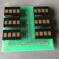
Voorkant 50.028
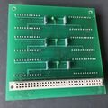
Achterkant 50.028


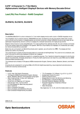
De displays op dit board zijn van het type DLO3416 datasheet. Deze hebben 6 datalijnen, een !WR lijn die aangeeft wanneer deze datalijnen gelezen moeten worden, 2 adreslijnen die aangeven welk van de 4 digits wordt aangestuurd, en 4 chip-enable lijnen die gebruikt kunnen worden om individuele displays aan te sturen. CE1 en CE2 zijn actief hoog, !CE3 en !CE4 zijn actief laag, op die manier kan door lijnen samen te nemen adressering gedaan worden.
Op het 50.028 board zitten de diverse Chip Enable lijnen dus ook aan elkaar op een manier dat adressering van de 6 individuele displays mogelijk is.
Ik reken de plek waar een "P" in de connector staat als pin 1, en tel vervolgens als volgt:
| 1 | 3 | 5 | ... | 63 |
| 2 | 4 | ... | 62 | 64 |

De pin-out wordt dan: (Let op, nog niet gecontroleerd! Dit is met een multimeter uitgepiept maar ik heb het display nog niet aangesloten/aangestuurd). Pinnen die aan elkaar zitten hebben 1 rij in de tabel. Pinnen die niet verboden zijn, zijn weggelaten. Voor de chip-enable lijnen is een eigen tabel
| pin(nen) | Display-pinfunctie |
|---|---|
| 1,2,3,4 | 5 V voeding |
| nc pinnen! | |
| 7,8 | !CLR (van alle displays samen) |
| 9,10 | !WR (van alle displays samen) |
| 11,12 | A1 (van alle displays samen) |
| 13,14 | A0 (van alle displays samen) |
| 15,16 | Chip enable, zie andere tabel (CE2 E,B,D ; !CE4 A,C,F) |
| 17,18 | Chip enable, zie andere tabel (CE1 D ; CE2 B ; !CE3 A ; !CE4 E,B) |
| 19,20 | Chip enable, zie andere tabel (CE1 B,F ; CE2 A; !CE3 C,E ; CE4 D) |
| 21,22 | Chip enable, zie andere tabel (CE1 A,C,E ; !CE3 B,D,F) |
| 23,24 | CU (cursor select) (van alle displays samen) |
| 25,26 | CUE (Cursor select) (van alle displays samen) |
| 27,28 | D6 (van alle displays samen) |
| 29,30 | D5 (van alle displays samen) |
| nc pinnen! | |
| 33,34 | D4 (van alle displays samen) |
| 35,36 | D3 (van alle displays samen) |
| 37,38 | D2 (van alle displays samen) |
| 39,40 | D1 (van alle displays samen) |
| 41,42 | D0 (van alle displays samen) |
| 43 | BL (blanking) F |
| 44 | BL (blanking) D |
| 45 | BL (blanking) B |
| 46 | BL (blanking) E |
| 47 | BL (blanking) C |
| 48 | BL (blanking) A |
| NC pinnen! | |
| 61,62,63,64 | GND |
Waarbij de adressering van de displays overzichtelijker te zien is als je het als volgt weergeeft:
| display | 15 | 17 | 19 | 21 |
|---|---|---|---|---|
| A | L | L | H | H |
| B | H | L | H | H |
| C | L | H | L | H |
| D | H | H | L | H |
| E | H | L | L | H |
| F | L | H | H | H |
De displays op de print zijn hierbij genummerd als
| A | B |
| C | D |
| E | F |

De displays zijn dus te adresseren door middel van de adreslijnen op pinnen 15,17,19,21 (chip enable lijnen). De digits binnen een display door middel van de A0 en A1 adreslijnen.
Om een van de hierboven ge-"transclude"d pagina's te wijzigen, bezoek de pagina via Categorie:DisplayBoardsSchiphol.
Datasheet displays
50228 and 50229 use PD44x (PD4435, red) displays. 50.028 and 50219 use DLO3416 (red). 50227 uses DLO1414 (smaller 4-digit display, red). 7003-assy uses PD2473 (green) (PD44x datasheet).
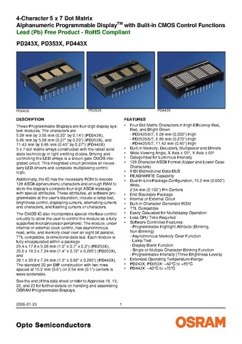 PD44x
PD44x
Code in https://github.com/MakerSpaceLeiden/AirtrafficControlDisplaysSchiphol/blob/main/shared/pd44.c
Various people hack them
- https://www.flickr.com/photos/okini393939/5148872258
- https://github.com/TiNredmc/PD443X_Lib
- https://github.com/TiNredmc/PD443Xclock
Requirements for development
In general an AVR compiler, baseline libc and a programmer is needed.
You will need an AVR programmer. A simple one like [USBasp] should do. It has been tested against an [SK500].
For more complex interactive 'talking' to it (e.g. if you wanted to hook it up to FlightTracker, your clock or a calendar) - you will need a 5 volt tolerant [USB to TTL Serial] adaptor (or connect something like an Arduino or ESP32 to it. You may need a 3/5 volt [level] [converter] in that case).
You will also need 6 'dupont' cables -- they are [best] [bought] [in bulk].
Requirements Apple MacOSX
When using ports install:
sudo port instal avr-gcc avr-libc avrdude
Also install avr-binutils and avr-gdb if you want to do debugging.
Requirements Linux
In general something like
   sudo apt-get update
   sudo apt-get install avr-libc binutils-avr gcc-avr avrdude
should do.
Requirements Windows
The canonical tool is [AVR Studio] and the process is explained on [this page].
That said [PlatformIO with AVR] seems to be becoming the popular choice nowadays. See this [starter documentation].
      [env:schiphol]
      platform = atmelavr
      # board = atmega161
      board_build.mcu = atmega161
      board_build.f_cpu = 8000000
      upload_protocol = custom
      upload_port = usb
      #         $(AVRDUDE) $(AVRDUDEFLAGS) $(AVRDUDECONF) -c avrispmkII -p m161 -U flash:w:$<:i
      upload_flags =
          -C
          $PROJECT_PACKAGES_DIR/tool-avrdude/avrdude.conf
          -p
      	m161
          -c
          	avrispmkII
      upload_command = avrdude $UPLOAD_FLAGS -U flash:w:$SOURCE:i