VK2000-build
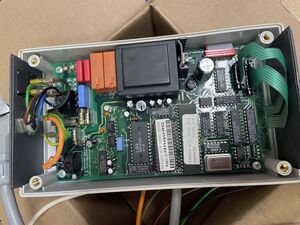
This page documents the fire control of the Ceramic Oven / Keramiek Oven. See this page for instructions on using the oven. And the details on the fire control computer are here.
Inhoud
[verbergen]Wiring VK2000 units
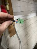
- N and single 220volt L via switch; black and blue
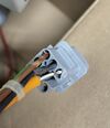
- 2x for the S-type thermocouple - orange cable; white (-) and brown (+)
- 2x Normally open relays to switch a load contactor
- Earth wire
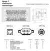
The old unit used an Harting HAN7Da connector; which was replaced.
RCD / Aardlekschakelaar
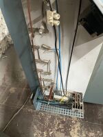
40A, 500mA residual current detector/aartlekschakelaar in de loop. It sits in the path to the 4+1 IEC wall socket.
Node
An Next generation node board is used (Node Ceramic - that is currently AC powered. This will be changed to PoE; so we can get something like 12 volts to read the kWh meter properly. This will require replacing the two relays.
kWh meter
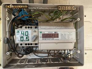
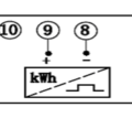
Dit is een DTS353 -- https://www.rdlmeters.com/product/dts353/ met een Watt-uur puls uitgang.
Deze is vermoedelijk low-voltage open collector. Plan is te beginnen met 3v3 volt en een 4.7 kΩ pull up resistor on the IO port of the node..
Wiring kWh meter too ACNode
Zwarte audio kabel die rechts boven de kast in komt.
- Schroef terminal 9; Plus; center van coax (rode terminal), dan naar rood van het plugje aan de kant van het PCB
- Schroef terminal 8; Minus; aarde van de coax (zwarte terminal), dan naar bruin van het plugje aan de kant van het PCB
There is a 4k7 resistor to the 5Volt (was 3v3) -- it is not yet reliable.
Sensor / Thermocouple
The device shows that it expects a "Pt 10.4" thermocouple. Markus Kohl (mkoehl at bentrup punt de), the expert at Bentrup.de confirmed that "Yes "Pt 10.4" stays for a Thermocouple Typ"S"!".
I.e. Platinum / 10% Rhodium
Currently in use:
- Nenniger GmbH, Berlin, Hochtemperatur S-Type Thermocouple. We may need to order a longer one (about 25 euro's) to make it stick out further in the oven.
- Special type of cable for this (orange - 'compensation wire'). Additional length was ordered from Conrad: "600889 Thermo-elementkabel" - around 5 euro/meter.
It was glue-ed with thermo-plaster/glue into the old holder.
The official wiring colours follow IEC 60584-3:2021 and are for S wire:
We assume that this type of cable needs to be used - given the circuit in the Bentrup. Using the old cable gave errors.
Load Limiter
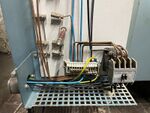
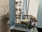
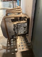
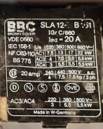
Standard machine load (Ampere) limited; with signalling NC contact part of the interlock & NO contact for indication. Must be reset by turning the knob back to '1'
Load limiter initially set at 10A; dropped during a FULL firing. Changed to 13A.
Heat Alarm
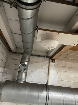
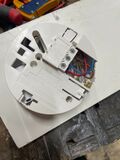
een FIT-NP5R dry-relay (NO, NC) sokkel met een FITH-23010 hitte sensor.
Heat Alarm Manuals as shipped
Actual manuals that were shipped with the unit (please keep)
Heat Alarm - Wiring
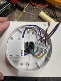
- Mains - 'tick' cable going to distribution panel
- L -- Phase 220v, Brown
- N -- Neutral, 220v, Blue
- Earth - terminated, Yellow
- Alert-signal, white -- not connected
- Dry relay - galvanically separate from mains - 'thin' cable going to oven control box
- Black - common
- Red - Normally open
- Blue - Normally closed
Thermal fuse
There is a thermal fuse in the interlock/relay control wire insithe the oven; near the lid-switch.
Currently set at around 77C.
Spare fuse(s) are placed in a small plastic bag in the large switch box (the one on the Succobus).
VK2000 Control signals
Our version has 2 relays; with an NO to the 'L'. The first relay controls the heating - the second one is simply on when a firing cycle runs; and off once completed or when you abort to cycle. E.g. as to, for example, operator an extraction fan or a mechanical lock on the door o the kiln.
- Earth wire (yellow/green)
- Wired to a distribution bar on the back panel
- Neutral wire (for the AC/DC) (blue)
- Wired post the main switch
- L wire (for AC/DC and as the feed of the relay outputs) (brown)
- Wired post the main switch, current limiter and Safety Relay
- Relay 1 out -- switching to L (black) -- this relays goes on and off throughout the firing cycle; it is wired to a PID for temperature control.
- Wired to the main control relay via the red cable *inside* the oven
- Relay 2 out -- Switching to L (green)
- Wired to Opto1 of the Node Ceramic. This relay goes on at the start of the programme; and off once the firing cyclus is complete.
- Purple wire - not connected
- Orange wire - white/brown - Pt
- wired to the Pt sensor inside the Oven
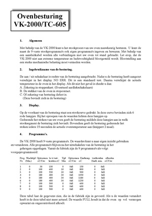
Manual
Wiring Oven side
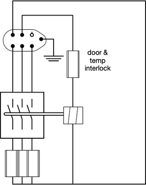
Harting style 6+1 connector carrying 3 phase power and relay control signal
- 2 pins for Neutral and Switch (relay)
- 3 pins for the 3 phases
- E pin for Earth
- The relay control runs through a clickson/temperature-fuse and a NO pushbutton that is pushed closed by the lid being fully down.
todo
Probably needs a snubber
Risks
Inherent
- Heat runaway (CPU fault, contacts welded)
- Faulty thermocouple causing heat runaway / instability / cracking
- Contact with water/leak
- Material falling onto it / other people working too near / unclear that is hot
- Touching hot material in oven / once out of oven
Operator driven
- Flammable material near
- Hot handles, etc
- Dust
- Unclear it is on / hot
- Opening while hot
- Bare wire touching
- Looking into it / infrared radiation
- Toppling, bumping, people/things pushed into it
- Welding equipment nearby that may be flammable
- Use of the corner by a third party for flammable things (e.g. spray painting)
- Use when broken
Measures and Controls
- Touching bare metal electric coils / electrocution risk
- Equipment grounded, fully metal or nonconductive enclosures
- Instructions
- Interlock on door/lid (touching bare metal electric coils)
- Earth leak trip/detector (touching bare metal electric coils)
- Touching bare metal during filling
- Instructions
- Interlock on door/lid (touching bare metal electric coils)
- Earth leak trip/detector (touching bare metal electric coils)
- Touching bare metal during maintenance
- System not wired - main 3+1+N IEC plug that can be used to fully disconnect the unit (the wire to the kWh meter is galvanically isolated)
- Control enclosure can only be openend with mains switch physical in the off position; additional mechanical shielding/cover on incoming mains to IEC plug
- Runaway heat
- VK2000 validates heat/cool & stops firing when outside control range
- Heat fuse directly on the firing relay control in the Kiln itself (set well below 100C; i.e. will block control currents well before the control electrics itself is affected by the heat)
- Heat sensor above oven that operates independent of the firing control
- Overcurrent protection that operates independent of the firing control and heat sensor
- Check ACNode for current & firing - and stops firing when outside control range (TODO)
- No unknown/uncontrolled states on powerup / after powerlock (TODO)
- VK2000 and Oven are designed to fail safe
- Oven designed to fail safe
- Emergency button
- Present and relatively far from oven / some shielding by beam
- Lockout / tag out
- The main switch can be locked with a padlock to lock/tag the machine out in the 'off' position
- mijn.makerspaceleiden.nl allows for locking a machine put by placing it in do-not-use/maintenance mode (which will also block powering it on).
- Preventing burns and people looking into the fume-hole without protection.
- Signage (eye, heat, ..)
- Instruction
- Bumping/tipping/etc risks
- Safe location, 2 sides wall
- Removal overly hard - presence of beam, welding table, controls screwed to the wall & limited cable length. Spacers behind/between legs and wall
- Placard with 'oven is in use / hot' is part of the oven
- Instructions to use it.
- Personal Safety Equipment (gloves, safety gogles, welding mask/googles)
- Part of the instructions
- 'on loan' material always available & nearby
- Signage (eye, heat, ..)
- Operator errors
- Mandatory Instructions
- Tag system
- Instructions can only be entered by those who had instruction or with trustee override
- Lockout by physical key (on the main switch) or via the tag system when broken
- Set of processes for lockout & facilities for this (3 three lockout boxes at the front door)
History
- 2024/10/29 - Thermal fuse replaced (Marc Paulusma, Dirk-Willem van Gulik)
