Payment Terminal with TFT screen: verschil tussen versies
(→Building one) |
|||
| Regel 4: | Regel 4: | ||
[[Bestand:Betaalterminal-prototype-dis-2.jpg|300px|Huidige versie, voor onderdelen betalen]] | [[Bestand:Betaalterminal-prototype-dis-2.jpg|300px|Huidige versie, voor onderdelen betalen]] | ||
| − | Prototype voor bier/koffie afrekenen in de voor-ruimte. En achter bij de WC, voor afrekenen moeren, boutjes, etc uit de grijpvoorraad. Zie [[SpaceTegoed]] voor een overzicht/plan, [[Payment and Paring REST protocol]] for the protocol and [[https://github.com/dirkx/makerspaceleiden-payment-node github for code]]. Screen documentation is at https://www.displayfuture.com/Display/datasheet/controller/ST7735.pdf | + | Prototype voor bier/koffie afrekenen in de voor-ruimte. En achter bij de WC, voor afrekenen moeren, boutjes, etc uit de grijpvoorraad. Zie [[SpaceTegoed]] voor een overzicht/plan, [[Payment and Paring REST protocol]] for the protocol and [[https://github.com/dirkx/makerspaceleiden-payment-node github for code]]. Screen documentation is at https://www.displayfuture.com/Display/datasheet/controller/ST7735.pdf. Part of the [[SpaceTegoed|Space tegoed payment system]]. |
Er is een `extra' unit om mee te ontwikkelen en te debuggen. | Er is een `extra' unit om mee te ontwikkelen en te debuggen. | ||
Huidige versie van 20 jan 2024 om 18:10


Prototype voor bier/koffie afrekenen in de voor-ruimte. En achter bij de WC, voor afrekenen moeren, boutjes, etc uit de grijpvoorraad. Zie SpaceTegoed voor een overzicht/plan, Payment and Paring REST protocol for the protocol and [github for code]. Screen documentation is at https://www.displayfuture.com/Display/datasheet/controller/ST7735.pdf. Part of the Space tegoed payment system.
Er is een `extra' unit om mee te ontwikkelen en te debuggen.
Inhoud
Versions build
There are currently two in use
- In de schone ruimte; board revision 4, Firmware 1.05,
80:7D:3A:D5:46:8C - Achter, bij de grijpvoorraad. board revision 3, Firmware 1.05
C8:C9:A3:CB:B6:7C,192.168.6.200 - Ontwikkel/test unit; board revision 4, Firmware 1.XX
0:5A:1B:67:21:AB-- niet aangesloten normaal gesproken.
Terminal met beeldscherm


Video: https://player.vimeo.com/video/628163050?h=e344411a85
Bij dit type terminal kun je kiezen wat je betaald met een "+" en "-" knop.
- Het display toont de text 'Swipe to Pay" met daaronder iets als "Bier" of "Koffie" en het bedrag.
- Met de + en - knop blader je door de opties. Totdat je de juiste hebt.
- Swipe je tag langs de terminal.
- Indien het bedrag groter is dan 5 euro komt de vraag "Pay <bedrag>" -- OK of Cancel. Bij cancel ga je terug naar stap 1. Bij Pay naar de volgende stap.
- Het display toont `paying' ... en tot slot 'Paid by <je eigen naam>'.
- En gaat daarna terug naar stap één.
Indien er iets fout gaat zie je op het scherm een foutmelding. Op de server wordt bijgehouden wat er fout ging. Als gebruiker kun je in dit geval niet veel meer doen dan cash betalen, het bij de mailing lijst melden, of het later weer proberen. Na een minuut geen gebruik gaat de terminal ook altijd terug naar stap 1.
Troubleshooting
First thing to check are the pairing in the CRM and then check the logs on the server /var/logs/crm/crm.debug and the MQTT logs in /var/log/mqtt
These will tell you recent reported states and the most recently known IP addresses claimed.
It is possible to 'telnet' into these units (on the normal telnet port #23) and see what normally would come out of the serial port. The units also sent their logging to syslog (to the spaceserver, 192.168.6.1).
Check MQTT, the firewall, use a [MDNS] [resolver] (or simply the Arduino IDE) to discover their IP address. You can do this from the RaspPi next to the VinylCutter / Vinylsnijder.
| MAC | Versie | Mac address | IP address |
|---|---|---|---|
| Grijpvoorraad | 1.04 | C8:C9:A3:CB:B6:7C | 192.168.6.200 |
| Voorruimte | 1.04 | 80:7D:3A:D5:46:8C | 192.168.6.189 |
Version deployed as of November 2021: https://github.com/dirkx/makerspaceleiden-payment-node/releases/tag/v1.04
A typical session looks like:
$ telnet 10.13.0.241 23
unset@tft-1.04-c767b4 Telnet connected C8:C9:A3:C7:67:B4
10.13.0.1:58451 Connected.
fetching prices
HTTP reponse: 200
Payload: {"name": "tft-1.04-c767b4", "description": "Laswerkplaats", "pricelist": [{"name": "mig-gas", "description": "Mis gas, beetje", "price": "1.00", "default": true}, {"name": "C3H8", "description": "Veel gas (mig, tig of propaan)", "price": "5.00"}, {"name": "meer mig-gas", "description": "Mig gas; meer", "price": "2.50"}]}
parsed as json fine
     mig-gas * 1.00
        C3H8   5.00
meer mig-gas   2.50
Pricelist fetched; 3 items
got prices
Bad read (was card removed too quickly ? )
Furthermore - if you connect to space.makerspaceleiden.nl via MQTT - then you can also see the output:
TOPIC: ac/log/tft-1.04-cbb67c
   Grijpvoorraad {
  "rfid_scans": 0,
  "rfid_misses": 0,
  "ota": true,
  "state": 3,
  "IP_address": "192.168.6.200",
  "Mac_address": "C8:C9:A3:CB:B6:7C",
  "Paid": 0,
  "Version": "1.04",
  "Firmware": "tft-1.04-cbb67c",
  "heap": 139667
}
Any error message (post joining the Wifi network) will show up here. If the issue is prior to joining WiFi - you will have to connect a USB cable (Baudrate 115200, 8N1). The Raspi has the right drivers installed.
Finally - all logging is also sent to syslog on the local server in the space; at Facility local0 (16), Severity debug (7).
Building one

If you need to build one - contact Dirk-Willem van Gulik - as we have a few `one board' versions that perhaps can be used (https://oshwlab.com/dirkx/stm25-reference-design_copy)
Activatie
Zie SpaceTegoed#Het_koppelen_van_betaalterminals_aan_het_betaalsysteem voor de activatie procedure. Overleg even met het bestuur om je pas ge-accordeert te krijgen voor test/initiatie & test betalingen.
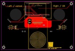
Lasercut prototype


Left is as currently used; right is a more spash proof version meant for plexiglass.
Settings for the laser cutter: Letters; 1500 at 30%; holes 1000 at 60% from 3mm plexiglass. Order: letters, small holes, big holes and then the outline.
Buttons are ~29-30 mm arcade style pushbuttons.
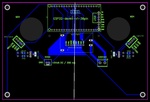
See also this PCB: https://easyeda.com/dirkx/payment-terminal and https://oshwlab.com/dirkx/stm25-reference-design_copy
Bill of material


In decreasing cost
- ESP32, 38 pin version; ~7 euro (https://www.amazon.nl/gp/product/B074RG86SR)
- 1.77" 160(RGB)x128 TFT screen; ~7 euro (https://www.amazon.nl/AZDelivery-Display-128x160-compatibel-Inclusief/dp/B07TJGF8HS). Pulls 40+ mAmp; too much for GPIO direct drive.
- 1 RFID reader; ~2.50 Euro; (https://www.amazon.nl/gp/product/B074S9FZC5)
- 2 arcade buttons; ~ 2x2 Euro, donation to the space van Leon. LEDs pull about 11 milliAmps (direct GPIO drive ok). https://www.amazon.nl/EG-booglichten-ingebouwde-schakelaar-verlichte/dp/B01N11BDX9
- Stukje plexiglas uit lasercut restjes
- 3D printed spacers/pinnen van plastic voor RFID reader mount.
- 4 boutjes/moertjes 2.3mm uit space voorraad voor scherm - mag wel metaal zijn.
- Wat draadjes uit electronica voorraad.
- USB kabeltje en adaptortje (lag op tafel).
- Restje hipster hout
In versie 2
- Added capacitor across 5volt
- Added capacitor (10uF) across 3v3 to the TFT
- Added 2 resistors of 2k2 to pull the GPIO pins of the buttons low; as they now just 3 (rather than 4) wires; and we need the common wire to be 5Volt as the LEDs won't light up at 3v3.
Totaal: < 20 euro; 10 minuten 3D printen; 15 minuten lasersnijden; 15 minuten hout zagen, nachtje drogen (dank aan de Bandspanner/Belt clamp strap) en 30 minuten solderen/assemblage.
Wiring
Code to check buttons and backlight wiring:
void setup() {
  Serial.begin(115200);
  Serial.println("Compiled: " __DATE__ " " __TIME__);

  pinMode(32, INPUT);
  pinMode(33, INPUT);
  pinMode(4,OUTPUT);
}

void loop() {
  Serial.print(digitalRead(32));
  Serial.print(" ");
  Serial.print(digitalRead(33));
  Serial.println();
  digitalWrite(4,(millis()/1000) & 1);
  delay(200);
}
This will show which buttons are pressed and will flash the TFT.
EPS32 board


| GPIO | Functie |
|---|---|
| Vin | to buttons LED (first revision), to power supply (5V) |
| 3V3 | To both boards, VCC, Both Anodes TFT (8,9), to buttons LEDs (revision 3, later), to buttons (rev2) |
| GND | To buttons, to both boards (rev 1/3) |
| 23 | LED button 1 |
| 22 | LED button 2 |
| 32 | Switch button 1; with pull-up & connect to GND for board v1; with 2k2 resistor to ground and switch wired to 5V with 1k2 for revision 2. |
| 33 | Switch button 2; with pull-up & connect to GND for board v1; with 2k2 resistor to ground and switch wired to 5V with 1k2 for revision 2. |
| 12 | TFT_MOSI |
| 14 | TFT_SCLK / clock |
| 26 | TFT_CS, SS, Select |
| 27 | TFT_DC, A0, data/command |
| 4 | TFT_BL, backlight, Revision 3 only. |
| 2 | TFT_RESET |
| 16 | RFID_SCLK |
| 16 | RFID_SCLK |
| 5 | RFID_MOSI |
| 13 | RFID_MISO |
| 25 | RFID_CS, SS, SDA |
| 16 | RFID_RESET |
| 3 | RFID_IRQ - label is RX0 |
Changes revision 3
- 1k2 / 2k2 resistor divider on the switches; as they are not reliable right now.
- Backlight screen takes about 40mA max; the max draw on the EPS32 is 40mA too; so add backlight switch off with 8-20 ohm resistor or drive it through a fet/transistor; on GPIO 4.
Button 1

Wiring for board 2; were we make use of the GPIO _in_put being 5Volt tolerant. And an extra 2k2 Resistor was added to the ground on the PCB.
| pin | kleur | label | functie |
|---|---|---|---|
| 1 | geel | Switch | GPIO 32 |
| 2 | zwart | LED A, Switch | 5V |
| 3 | rood | LED K | GPIO 23 |
Button 1
Wiring for board 2; were we make use of the GPIO _in_put being 5Volt tolerant. And an extra 2k2 Resistor was added to the ground on the PCB.
| pin | kleur | label | functie |
|---|---|---|---|
| 1 | geel | Switch | GPIO 33 |
| 2 | zwart | LED K, Switch | GND |
| 3 | rood | LED A | GPIO 22 |
RFID

| pin | kleur | label | functie |
|---|---|---|---|
| 1 | zwart | SDA | RFID_CS, GPIO25 |
| 2 | rood | SCK | RFID_SCLK, GPIO16 |
| 3 | wit | MOSI | RFID_MOSI, GPIO5 |
| 4 | geel | MISO | RFID_MISO, GPIO13 |
| 5 | orange | IRQ | RFID_IRQ, GPIO3, Labeled RX0 |
| 6 | groen | GND | GND |
| 7 | blauw | RESET | RFID_RESET, GPIO 17 |
| 8 | paars | 3V3 | 3V3 |
Scherm

| pin | kleur | label | functie |
|---|---|---|---|
| 1 | zwart | GND | GND |
| 2 | rood | VCC | 3V3 |
| 3 | wit | SCK | TFT_SCLK, GPIO14 |
| 4 | geel | SDA | TFT_MOSI, GPIO12 |
| 5 | orange | RES | TFT_RST, GPIO2 |
| 6 | groen | RS | TFT_DC, GPIO27 |
| 7 | blauw | CS | TFT_CS, GPIO26 |
| 8 | paars | LED A | 3V3 with Capacitor. |