Megger / Insulation Meter
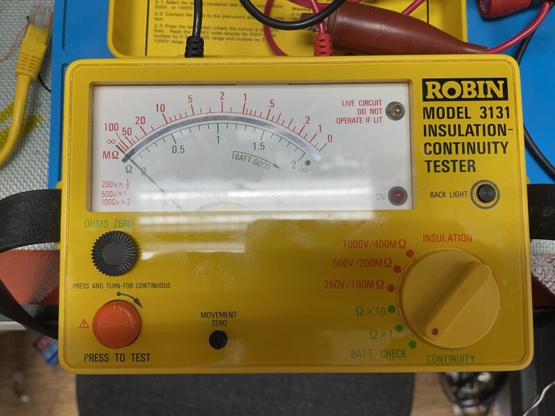
A "Megger" or Insulation meter [wikipedia] - can be used to measure the isolation; for example of our 3 phase motors in the Metal Mitresaw, the Circular Table Saw or any of our normal 2 phase electric machines. It helps ascertain that the device is safe to use.
It works by putting 500V or a 1000V across the measuring probes and then checking, measuring, if the resistance is well in the high mega ohms.
This means that, during measurement, there is a nasty, (current limited) 1000V, across the probes !
It is not safe/pleasant to hold the probes/touch exposed conductive parts during measurement
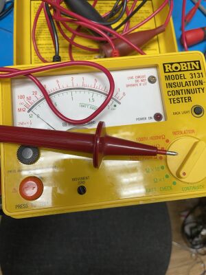
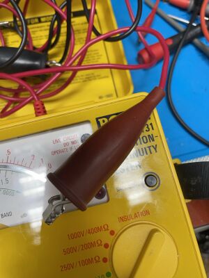
So you must use well isolated test probes - and not hold these in your hand. The second reason to use isolated clamps is that it is always possible you made a mistake and did not actually unplug the machine; or otherwise are measuring life voltages.
Measuring Isolation/Leakage
- Set the meter to the battery test.
- Press the orange button and make sure it is in the `good' range.
- Set the meter to 500V or 1000V.
- Press the orange button shortly while nothing is connected.
- Check that the dial `just' moves. If not - use the back zero adjust so that it just moves if you press the orange button.
- Check that the red 'ON' LED is off. If not - turn the orange dial to make it release.
- Visually check the probes - there should be no cracks or bare metal visible except at the very ends
- Connect the probes to the device.
- On the machine you want to test - make sure it is as switched 'on' as is feasible (as otherwise we just test the isolation of the power cable). E.g. on a corded drill with grounding - switch & lock it in the 'on setting'. Know that on some of our 3 phase machines - the build in safeties prevent exactly this. On those machines the testing process requires a second set of test where you connect on the motor directly or after the safety relay (and usually requires removing the star/delta bridge).
- Connect one probe to earth and the other to one of the pins of the plug.
- Make sure your hands are no-where near the probes - as in the next step you will energise them to a thousand volts - which hurts.
- Step back. Press the orange button. Be a bit careful, There is now a 1000V across the probes
- Read out the resistance; it should be in the high mega ohms (note the red scale multiplier):
- So if you have it set to 1000V; and it reads '5' you have to multiply the value by 2.
- So if you have it set to 250V; and it reads '5' you have to divide the value by 2.
- Let go of the orange button
- Now test Earth versus the other pin.
- Where relevant; e.g. when the metal housing is not grounded; also measure between the housing an the pins
Typical use
It is common in workshops to test all electrical equipment once a year.
For this the machine MUST be disconnected from the mains -or- the fuses in the fusebox need to be removed.
For most of our three phase motors this usually means disconnecting the Star/Delta cross connects on the motor & doing each 3 versus each other and versus the grounding. And then rewiring it again.
Usually a good idea to take a photo of the wiring before you disconnect.
So in that case you'd remove the wires from both sides of all 3 coils. That leaves you with 6 contacts. Often called something like A1, A2, B1/2, C1/2 or P1/2, Q1/2, R1/2 or similar (or U,V,W).
You then check that A1/A2 are having a very low conductivity with the continuity check. And same for B1/2 and C1/C2. It is also good to check motor earth/casing and earth. And earth near the motor and earth in the plug.
Next you check that you measure `no continuity' i.e. high resistance value (i.e. no short) between A and B, B and C and C and A. As well as between A and earth, B and earth, and C and earth.
You then put the meter in isolation mode and repeat the previous checks; but now for more `real'.
I.e. wire one wire up to A and the other to B. And check you get that you STILL get a high number of megaohms; Same for B to C and C to A. And between A and earth, B and earth and finally C and earth. Values should be well above 2 Mohm and similar if the motor is dry and has ran in the last weeks.
Set
- Pouch with three test wires
- 1 black wire with a black crocodile clip
- 1 red wire with a red crocodile clip
- 1 red wire with a stift.
- Robin 3131 Unit itself
- Leather strap for carying
- Paper Manual
Safety
The unit is class 4 - so mandatory instruction reading.
The unit has an extra sticker to alert the user to this fact & the fact that there can be a 1000Volt.
The actual situation is not that dire - as the 1000 Volt is current limited to 1mAmp (assuming no faults) and a healthy person will generally in a reflect remove your hand or other exposed body parts.
Also note that it is quite easy to make the mistake that you think that a particular machine was unplugged; but it is in fact, still plugged in; with some of the wires life at 235V or 400Volt.
Documentation
Full manual
Service and Calibration manual
History
Bought by the space early 2024
Voltages and resistance up to 10Mohm last checked 1/1/2024
This equipment is safety category 4:
- In-person, instructions strongly advised but not mandatory.
- Reading, and following, the instructions on the Wiki is mandatory!
This equipment is Noise Category 3: Can be used at all hours. No limits.
 Handle with care.
This is a precision tool with exact dimensions and straightness.
That means: handle it gently, don't hammer on it or use it as a crowbar and so on.
(if you need a crowbar - these are wonderful for that!)
It is very important that if you accidentally drop it or think it may be out of line
- either mark the tool very clearly...
- or report this to the mailing list...
...so that your fellow makers do not ruin their work.
