PowerNodeBlue-bringup: verschil tussen versies
(→Improvements) |
(→Features) |
||
| Regel 47: | Regel 47: | ||
# Add the word 'OFF' to the labels of all bridges in the PoE field (and not just the top one) | # Add the word 'OFF' to the labels of all bridges in the PoE field (and not just the top one) | ||
| − | = Features = | + | = Soldered on Features = |
| − | == Board 001 == | + | == Board Blue-001 == |
* OLED screen, ESP32-WROOM-DA, Buzzer, override contacts | * OLED screen, ESP32-WROOM-DA, Buzzer, override contacts | ||
Versie van 5 feb 2025 om 20:24
15 units; 25/01/23 fab date.


Inhoud
[verbergen]Initial Bringup / checkout
Board 001 (selected as sacrificial):
- Optically checked soldering/board as is
- Plug in USB-C
- Check 3v3 and 5v power; check red LED comes one.
- Check for magic smoke/things getting hot (nothing should)
- check detection of serial port/driver. It won't have any output at this point
- PoE powering
- Solder in RJ45 connector
- Place solder bridges Vpwr, V5 to VPOE/VPOE5 in Source field
- Do not place the Vpwr/5V bridges in the PoE field - these should be better labeled: e.g. have an 'OFF' text added to them like the one just above.
- Plug in PoE ethernet; check voltages: 5V, 3v3 and Vpwr==5V
- ESP32
- Solder in the ESP32 -- revision used:
- Chip is ESP32-D0WD-V3 (revision v3.1)
- MAC: 08:a6:f7:b0:72:ac
- Unplug PoE ethernet; plug in USB;
- Check 115200 baud visibility of ESP32 (press reset if needed). Should see
ets Jul 29 2019 12:21:46 ... rst:0x1 (POWERON_RESET),boot:0x13 (SPI_FAST_FLASH_BOOT)
- Check upload with default Arduino example `Blink' app against LEDs set to OUT1/OUT2 (GPIO 16, GPIO4) with ESP32 -> ESP32-WROOM-DA module with settings
 and
and 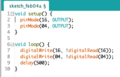 .
. - Uploading at 115200 should work.
- If it fails - go drop speed
- For proper board with proper/non-counterfeit chips - 921600 baud works stable and well.
- Check the schematic for the 33 Ohm resistors that are supposed to help with the impedance/driving.
- Solder in the ESP32 -- revision used:
- PoE and ESP32
- Remove from USB; plug into PoE and check LEDs start flashing as soon as the power LED comes on.
- From this point on - use a Galvanic USB isolator when connecting to the board with Ethernet plugged in.
- Solder in Buzzer, OLED display (if needed), buttons, connectors
- Test with plain PowerNode install & check screen & menu cycling
- Check RDIF
- Holding an RFID card should cause two beeps. Use the VNA - Vector Network Analyser with this information to check.
- Check IP allocation on screen/serial and check web interface
- (Optional) solder on final power selection, fuses, sensors, etc.


Problems during bringup
- Accidental solder bridge between pin 13/14 of ESP32 made it look like the switch was not mechanically not working (stuck in 0).
Improvements
- Add the word 'OFF' to the labels of all bridges in the PoE field (and not just the top one)
Soldered on Features
Board Blue-001
- OLED screen, ESP32-WROOM-DA, Buzzer, override contacts
- PoE powered; VUSB allowed
- 100k Potentiometer for voltage setting
- Vpwr Voltage set to 12V
- 5A/250VAC relay; 12V coil
- Error LED, Output 1, 2 LEDs on front (all red)
- Extra LEDS: Red,Red,Red,Orange,Green (Hearthbeat)
- Normal green connector; `arrow' to side of board