POESP-board 1.0: verschil tussen versies
| Regel 9: | Regel 9: | ||
Stepdown from 48V PoE to 3v3 is done in two steps, the intermediate voltage can be set at any voltage between 5 and 24V. | Stepdown from 48V PoE to 3v3 is done in two steps, the intermediate voltage can be set at any voltage between 5 and 24V. | ||
| − | This design and | + | This design and formfactor is abandoned by me, there might be an improved 2.0 in the future (but please do not hold your breath .. :-) |
| − | There were about 10 prototypes | + | There were about 10 prototypes assembled. There are no PCB's available, but the pastastencil is @ Makerspace Leiden. |
Main components: | Main components: | ||
| − | * [ | + | * [https://www.espressif.com/sites/default/files/documentation/esp32-wroom-32_datasheet_en.pdf| ESP WROOM 32 module] |
* [http://ww1.microchip.com/downloads/en/DeviceDoc/8720a.pdf| LAN8720] ethernet phy | * [http://ww1.microchip.com/downloads/en/DeviceDoc/8720a.pdf| LAN8720] ethernet phy | ||
* [https://www.mouser.com/ds/2/336/-610985.pdf| JD0-0004NL-X1] ethernet jack with built-in magnetics | * [https://www.mouser.com/ds/2/336/-610985.pdf| JD0-0004NL-X1] ethernet jack with built-in magnetics | ||
| − | * [ | + | * [https://www.ti.com/lit/ds/symlink/tps2375.pdf| TPS2375] POE controller |
| − | * [ | + | * [https://www.ti.com/lit/ds/symlink/lmr16010.pdf| LMR16010] primary stepdown, 48V POE -> 5 - 24V @ 1A |
* [http://ww1.microchip.com/downloads/en/DeviceDoc/20005004D.pdf| MCP16301] secondary stepdown, 5-24V -> 3v3 @ 600 mA | * [http://ww1.microchip.com/downloads/en/DeviceDoc/20005004D.pdf| MCP16301] secondary stepdown, 5-24V -> 3v3 @ 600 mA | ||
* [https://www.silabs.com/documents/public/data-sheets/cp2102n-datasheet.pdf| CP2102N] USB to serial interface | * [https://www.silabs.com/documents/public/data-sheets/cp2102n-datasheet.pdf| CP2102N] USB to serial interface | ||
Versie van 1 mei 2024 om 22:21
Inhoud
[verbergen]Overview
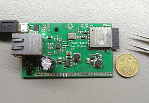
The POESP, for PoE-ESP, is a ESP32 breakout board with LAN and PoE. Please understand well this device is NOT insulated from the PoE, so use only in suitably insulated setups. DO note the "known problems". There is an usb interface for loading the firmware and debugging, be aware the ground of this interface might be at +48V from PE (or worse) as well ! So use a well-insulated laptop and/or do not use when powered by PoE. Stepdown from 48V PoE to 3v3 is done in two steps, the intermediate voltage can be set at any voltage between 5 and 24V.
This design and formfactor is abandoned by me, there might be an improved 2.0 in the future (but please do not hold your breath .. :-)
There were about 10 prototypes assembled. There are no PCB's available, but the pastastencil is @ Makerspace Leiden.
Main components:
- ESP WROOM 32 module
- LAN8720 ethernet phy
- JD0-0004NL-X1 ethernet jack with built-in magnetics
- TPS2375 POE controller
- LMR16010 primary stepdown, 48V POE -> 5 - 24V @ 1A
- MCP16301 secondary stepdown, 5-24V -> 3v3 @ 600 mA
- CP2102N USB to serial interface
Default SMD size is 0603.
GPIO =
| GPIO | Gebruik | Notes |
|---|---|---|
| 0 | INT | BOOT switch, high/Hz during normal boot; pulled low for bootloader |
| 1 | TX | UART / USB bridge en edge connector |
| 2 | - | vrij, op edge connector |
| 3 | RX | UART / USB bridge en edge connector |
| 4 | - | vrij, op edge connector |
| 5 | - | vrij, op edge connector |
| 6 | SCK | - |
| 7 | SD0 | - |
| 8 | SD1 | - |
| 9 | SD2 | - |
| 10 | SD3 | - |
| 11 | CMD | - |
| 12 | - | vrij, op edge connector |
| 13 | - | vrij, op edge connector |
| 14 | - | vrij, op edge connector |
| 15 | - | vrij, op edge connector |
| 16 | - | vrij, op edge connector |
| 17 | - | - |
| 18 | MDIO | Ethernet LAN |
| 19 | TXD0 | Ethernet LAN |
| 21 | TXEN | Ethernet LAN |
| 22 | TXD1 | Ethernet LAN |
| 23 | MDC | Ethernet LAN |
| 25 | RXD0 | Ethernet LAN |
| 26 | RXD1 | Ethernet LAN |
| 27 | CRS | Ethernet LAN |
| 32 | - | vrij, op edge connector |
| 34 | - | vrij, op edge connector, input ONLY |
| 35 | - | vrij, op edge connector, input ONLY |
| 36 | SVP | vrij, op edge connector, input ONLY |
| 39 | SVN | vrij, op edge connector, input ONLY |
Files
- Schema pdf: media:Poesp_1.0.pdf
- All CAD (Eagle) & CAM (Gerber) files can be found in our github repository: https://github.com/MakerSpaceLeiden/AccesSystem/tree/master/POESP_board
Sources of information used
About connecting the ethernet phy to the ESP.
- https://sautter.com/blog/ethernet-on-esp32-using-lan8720/
- https://www.waveshare.com/w/upload/0/08/LAN8720-ETH-Board-Schematic.pdf (note: not very accurate. Check config in the LAN8720 datasheet)
- https://en.wikipedia.org/wiki/Media-independent_interface#Reduced_media-independent_interface Interface between ESP and eth phy.
Suppliers
- Boards & stencil: Elecrow
- ESP32: AliExpress
- Other: Mouser
Known problems
- Not insulated. Groundloops during debugging easily fry the cp2102. Possible electrical safety issues.
- Rx/Tx leds do not work, fixing this requires programming the CP2102.
- The inter stage capacitors between prim. and sec. step down are too small. When the intermediate voltage is used, add an extra capacitor > 47 uF on the breakout board. Or place a larger capacity at a lower voltage if lower intermediate voltages, e.g. up to only 12V are required.
- The CP2102 USB interface has a tendency to release smoke due to its VBUS pin beïng pulled up to 5V by the USB connection while there is no 3V3 power supply available. So only connect USB while there is already PoE available and the power LED is on. Never short 3v3 while connected to USB.
