Node Spacedeur
192.168.6.29 cc:50:e3:8b:27:c7
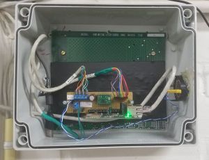
PoE powered Node on Ethernet for the door of the Space itself.
Inhoud
[verbergen]Electronics
Todo: Add schematic / POESP pinout NB: currently POESP v1.1 is used, as the USB/UART and Eth ICs are heating much less in this version. Schematics is for v1.0 (any major differences?)
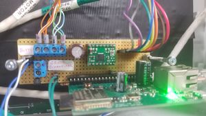
On the motherboard there are:
- resistor between "Set V++" and GND, setting the voltage output for the stepper motor ("Vmot" terminal of A4988) to 12V
- transistor for amplifying the pulses on GPIO16 for the buzzer
- pull-up resistor for MS1, ensuring the motor is making half-steps (?)
- R-C circuit for the a.k.a. "Grote Schakelaar"
- socket for A4988-type stepper motor driver
- header for the POESP board
- 8-pin RFID reader connector (brown/red pin is rightmost)
- 4-screw terminal for the stepper motor
- 2-screw terminal for powering auxillary devices (not connected)
- 2-pin terminal for the buzzer, which sounds when RFID is read successfully
- 2-pin terminal for the a.k.a. "Grote Schakelaar". High when switch is off (or wire broken). Goes low when the switch is on.
Pinout of the RFID reader connector
| pin | function |
|---|---|
| 1 | SDA |
| 2 | SCK |
| 3 | MOSI |
| 4 | MISO |
| 5 | IRQ |
| 6 | GND |
| 7 | RESET |
| 8 | 3v3 |
Pinout of ESP32
| ESP GPIO | function |
|---|---|
| 2 | Stepper DIR |
| 4 | Stepper Enable |
| 5 | Stepper STEP |
| 16 | Buzzer |
| 34 | Grote Schakelaar |
| 13 | MOSI |
| 12 | MISO |
| 14 | SCK |
| 15 | SDA |
| 32 | RESET (optioneel) |
| 33 | IRQ (optioneel) |
Stepper screw terminal
see labels on each wire, match with those on terminals
| Pin | functie |
|---|---|
| 1 | A - kleur onbekend |
| 2 | iA - kleur onbekend |
| 3 | B - kleur onbekend |
| 4 | iB - kleur onbekend |
Grote Schakelaar header
Cabling to the Grote Schakelaar; met deze [code].
Wiring:
| Pin | function |
|---|---|
| 1 | Switch; pulled up; to pin 34 of ESP 32 |
| 2 | Digital ground |
Interpretation of the voltages:
| Value | Interpretation | |
|---|---|---|
| low | Handle in horizontal position - space closed. | 
|
| high | Handle in vertical position -- open. | 
|
2-screw terminal
| Pin | function |
|---|---|
| 1 | 12Volt |
| 2 | power ground |
Software
Todo: currently Grote Schakelaar does not work (ESP needs to be coded to use GPIO34 signal / send info to MQTT). Partially coded up at https://github.com/MakerSpaceLeiden/AccesSystem/compare/master...dirkx:master -- but not tested yet.
Updated 2022/2/21 with https://github.com/MakerSpaceLeiden/AccesSystem/releases/tag/cache-fix-2022-02-22-1.01
Troubleshooting
You can now telnet to the node. Or open a webbrowser on the node directly: http://192.168.6.29. This will you show you the log.
Before unplugging anything else, always unplug the ethernet connector from the POESP board FIRST!
Never disconnect the stepper motor wires from their screw terminals if the ethernet cable is connected / system is powered
1. Reset the node by unplugging, counting to 30, and then re-plugging the (hopefully labeled, otherwise see space network diagram) PoE cable in the server cabinet. Check the green light on the POESP board. Wait 60 seconds before trying the RFID tag.
2. If the light on the POESP board is not on/green:
- disconnect ethernet. Disconnect stepper, RFID, and buzzer/schakelaar from the motherboard. Reconnect ethernet.
- If no light, disconnect ethernet and remove the A4988 stepper driver. Reconnect ethernet.
- If no light, unplug the POESP board from the motherboard, connect ethernet.
- If POESP led lights up - troubleshoot the corresponding module/connection.
- If POESP led does not light - POESP is dead. Get a spare from the read shoe box in the lower left drawer next to the electronics table. (If that does not solve it, mail "noc", it might be a POE/network problem)
- Inform "deelnemerlijst" (all members) of the situation, and make sure there is a spare POESP with firmware in the red shoe box when you are done.
(Todo: add instructions on how to upload firmware to POESP)

