PowerNode White - Configuration: verschil tussen versies
(→Pushbutton and LED connectors) |
(→Power setup / AC-DC and PoE Jumpers) |
||
| (9 tussenliggende versies door dezelfde gebruiker niet weergegeven) | |||
| Regel 18: | Regel 18: | ||
The jumps give the following options: | The jumps give the following options: | ||
| + | |||
| + | * PoE Negotiation off | ||
| + | ** When open; allow PoE negotiation | ||
| + | ** When soldered close; no PoE is requested. AC transformer assumed to be soldered onto the board. | ||
| + | * Write Protect | ||
| + | ** Only relevant if a i2c EEPROM has been soldered onto (default is not). Will write protect this EEPROM when soldered close. | ||
| + | * R81, R83, R132, R139 | ||
| + | ** When removed - will disable OPTO inputs | ||
| + | * R82 | ||
| + | ** When removed - will disable Current0 measurement. | ||
| + | * R84 | ||
| + | ** When removed - will disable RFID | ||
| + | * RJ2, RJ3 | ||
| + | ** When mounted - allows you to break out the RFID sensor from the middle and mount the RFID sensor outside; and the board inside. As used needed for the [[NodeSpacedeur]], [[NodeTussendeur]] and [[NodeVoordeur]]. | ||
| + | * JP4 -- Slowstart/PoE control 5 volt | ||
| + | ** No solder: normal PoE start (immediate) | ||
| + | ** Solder to SS - slow start PoE (recommended) | ||
| + | ** Solder to No - no PoE | ||
| + | * JP3 -- Slowstart/PoE control Power voltage | ||
| + | ** No solder: normal PoE start (immediate, always) | ||
| + | ** Solder to SS - slow start PoE (recommended) after 5 volt PoE is brought up. If no 5Volt - then no Power voltage either. | ||
| + | ** Solder to No - no PoE | ||
| + | * EXT to PoE | ||
| + | ** Allow external voltage to drive both DC/DC convertors (5V and Power voltage) | ||
| + | * INT to PoE | ||
| + | ** Allow AC/DC transformer to drive both DC/DC convertors (5V and Power voltage) | ||
| + | * Vpower to VEXT/POE/POE5/INT | ||
| + | ** Select the source of power for the power-voltage | ||
| + | * 5V to VEXT/POE/POE5/INT | ||
| + | ** Select the source of power for the 5V (and 3v3) electronics supply. | ||
| + | * OUT3, OUT4, ERR | ||
| + | ** When removed; a LED can be soldered on the other side of the board | ||
| + | * U39 / output 1 | ||
| + | ** Middle 2 pads joined: OUT1 is directly across the Normally Open of the relay | ||
| + | ** Outer 2 pads joined: OUT1's 2 outputs are connected to the N of the AC input and, via the relay, the L of the AC input | ||
| + | * U42 / output 2 | ||
| + | ** Middle 2 pads joined: OUT2 is directly across the Normally Open of the relay | ||
| + | ** Outer 2 pads joined: OUT2's 2 outputs are connected to the N of the AC input and, via the relay, the L of the AC input. The normally closed is wired the same way. | ||
| + | * MS1, MS2, MS3 | ||
| + | ** Sets the stepper speed - see A4988 documentation. | ||
| + | * LED9, LED10, LED11, LED12, | ||
| + | ** Optional leds on the back. | ||
| + | * IOA, IOB, IOC, IOD, IOE | ||
| + | ** When connector mounted - direct outputs of the AW9524 i2c expander; can drive an LED direct against the VCC or 5V. | ||
| + | * R58 | ||
| + | ** Wires copper area under RJ45 and Magnetics to a blob-smith plane/ground | ||
| + | |||
| + | == Voltage settings == | ||
| + | |||
| + | There are two DCDCs that take their input from the 48-60Volt pover ethernet. | ||
| + | |||
| + | The 5V DC/DC (and then down to 3v3) is fixed. The second DC/DC is fixed at 5 volts; but a resistor (or a potentiometer) can be soldered in to get a higher Power voltage (e.g. to drive relays: | ||
| + | |||
| + | {| class="wikitable" | ||
| + | |- | ||
| + | ! Resistor !! Voltage | ||
| + | |- | ||
| + | | 150k potmeter || 5-45+ volt (32 volt reliable max given wiring in the space) | ||
| + | |- | ||
| + | | 0 || 5V | ||
| + | |- | ||
| + | | 4k || 6V | ||
| + | |- | ||
| + | | 16k || 9V | ||
| + | |- | ||
| + | | 27k || 12V | ||
| + | |- | ||
| + | | 39k || 15V | ||
| + | |- | ||
| + | | 74k || 24V | ||
| + | |- | ||
| + | | 106k || 32V (practical max) | ||
| + | |} | ||
= Hardware options = | = Hardware options = | ||
The boards allow for various extra `options' | The boards allow for various extra `options' | ||
| + | |||
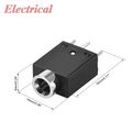
| + | == 15 pins Mains connector == | ||
| + | |||
| + | The main connector is a [https://nl.aliexpress.com/item/1005006345862685.html 15 pin, 3.5mm K2FEDGK connector/terminal block]. Approximate price is 1 euro. | ||
| + | |||
| + | [[Bestand: K2FEDGK-15pin.jpg|120px]] | ||
== Pushbutton and LED connectors == | == Pushbutton and LED connectors == | ||
| Regel 43: | Regel 122: | ||
== Pressure sensor == | == Pressure sensor == | ||
| + | |||
| + | There is room on the board for an i2c [https://nl.aliexpress.com/item/1005005347660680.html?gatewayAdapt=glo2nld HX710B] pressure sensor (around 1.50 Euro). | ||
| + | |||
| + | [[Bestand:I2c-hx701b.jpg|120px|i2c pressure sensor]] | ||
== OLED screen == | == OLED screen == | ||
| Regel 56: | Regel 139: | ||
[[Bestand:150x150.jpg|120px]] | [[Bestand:150x150.jpg|120px]] | ||
| + | |||
| + | XX insert Alex his design which we can print / change | ||
== Large 15 pin Connector == | == Large 15 pin Connector == | ||
| Regel 67: | Regel 152: | ||
Normal 2.5mm pitch | Normal 2.5mm pitch | ||
| − | == | + | == Relay == |
| − | + | A normal DPDT omron/schrack (plenty in the [[Elektronica Onderdelen|cupboard]]) or one of two types of Solid State relays - in line and 'box': | |
[[Bestand:SSRelay-1.jpg|120px]][[Bestand: SSRelay-2.jpg|120px]] | [[Bestand:SSRelay-1.jpg|120px]][[Bestand: SSRelay-2.jpg|120px]] | ||
| + | |||
| + | Of the small type - two will fit; of the big type - just one. However there is a 2.54 connector to move things off-board or to a din rail. | ||
| + | |||
| + | [[Bestand:dinrail-12v-1.jpg|120px]] | ||
Huidige versie van 26 apr 2024 om 14:42
Inhoud
Jumpers
Power Jumpers
The relays can be switched 'as is'; where the NO/C/NO or NO/C of either relay is mapped to pin 1,2,3 for the first relay and to pin 4 and 5 for the second relay. Or they can be mapped to the N/L of the AC input on pin 6 and 7. Diagram:...
Power setup / AC-DC and PoE Jumpers
Power can come from several sources; US, PoE, an external source and an AC/DC transformer on the board.
There are 2 power sets - one for the electronics (typically 5V down to 3v3) and one for the relays and other externals (typically 5v, 12v or 24 volt).
For PoE - unless a variable 68k resister (potentiometer) is mounted and R?? is removed - the external voltage is set to 5V by this register. The resistor allows for 5v to around 40v (given the general the max of PoE on our switch).
The AC/DC transformer can be anything between 3v3 and 12volt. For higher voltages - beware that the 3v3 regulator needs to step it down for the electronics.
The jumps give the following options:
- PoE Negotiation off
- When open; allow PoE negotiation
- When soldered close; no PoE is requested. AC transformer assumed to be soldered onto the board.
- Write Protect
- Only relevant if a i2c EEPROM has been soldered onto (default is not). Will write protect this EEPROM when soldered close.
- R81, R83, R132, R139
- When removed - will disable OPTO inputs
- R82
- When removed - will disable Current0 measurement.
- R84
- When removed - will disable RFID
- RJ2, RJ3
- When mounted - allows you to break out the RFID sensor from the middle and mount the RFID sensor outside; and the board inside. As used needed for the NodeSpacedeur, NodeTussendeur and NodeVoordeur.
- JP4 -- Slowstart/PoE control 5 volt
- No solder: normal PoE start (immediate)
- Solder to SS - slow start PoE (recommended)
- Solder to No - no PoE
- JP3 -- Slowstart/PoE control Power voltage
- No solder: normal PoE start (immediate, always)
- Solder to SS - slow start PoE (recommended) after 5 volt PoE is brought up. If no 5Volt - then no Power voltage either.
- Solder to No - no PoE
- EXT to PoE
- Allow external voltage to drive both DC/DC convertors (5V and Power voltage)
- INT to PoE
- Allow AC/DC transformer to drive both DC/DC convertors (5V and Power voltage)
- Vpower to VEXT/POE/POE5/INT
- Select the source of power for the power-voltage
- 5V to VEXT/POE/POE5/INT
- Select the source of power for the 5V (and 3v3) electronics supply.
- OUT3, OUT4, ERR
- When removed; a LED can be soldered on the other side of the board
- U39 / output 1
- Middle 2 pads joined: OUT1 is directly across the Normally Open of the relay
- Outer 2 pads joined: OUT1's 2 outputs are connected to the N of the AC input and, via the relay, the L of the AC input
- U42 / output 2
- Middle 2 pads joined: OUT2 is directly across the Normally Open of the relay
- Outer 2 pads joined: OUT2's 2 outputs are connected to the N of the AC input and, via the relay, the L of the AC input. The normally closed is wired the same way.
- MS1, MS2, MS3
- Sets the stepper speed - see A4988 documentation.
- LED9, LED10, LED11, LED12,
- Optional leds on the back.
- IOA, IOB, IOC, IOD, IOE
- When connector mounted - direct outputs of the AW9524 i2c expander; can drive an LED direct against the VCC or 5V.
- R58
- Wires copper area under RJ45 and Magnetics to a blob-smith plane/ground
Voltage settings
There are two DCDCs that take their input from the 48-60Volt pover ethernet.
The 5V DC/DC (and then down to 3v3) is fixed. The second DC/DC is fixed at 5 volts; but a resistor (or a potentiometer) can be soldered in to get a higher Power voltage (e.g. to drive relays:
| Resistor | Voltage |
|---|---|
| 150k potmeter | 5-45+ volt (32 volt reliable max given wiring in the space) |
| 0 | 5V |
| 4k | 6V |
| 16k | 9V |
| 27k | 12V |
| 39k | 15V |
| 74k | 24V |
| 106k | 32V (practical max) |
Hardware options
The boards allow for various extra `options'
15 pins Mains connector
The main connector is a 15 pin, 3.5mm K2FEDGK connector/terminal block. Approximate price is 1 euro.

Pushbutton and LED connectors
Normal two-pin XH 2.54 connector for the LED and for each of the push-buttons (inside the footprint). Same type as often used for fans on PCs.

Pushbuttons are 6x6mm standard pushbuttons; switch at least 10mm high. E.g. https://www.hobbyelectronica.nl/product/push-button-6x6x5/ or https://www.tme.eu/nl/details/1301.9304/microschakelaars-tact/schurter/ -- around 50cent.

External/separate current coil
The current coils can be on the PCB - but can also be replaced by a 3.5mm jacket and a standard pickup.
- 3.5mm jackets: https://nl.aliexpress.com/item/1005004035360795.html
- Current coil: https://nl.aliexpress.com/item/1005006003984501.html
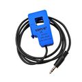


This is used on the Ceramic Oven its NodeCeramic.
Pressure sensor
There is room on the board for an i2c HX710B pressure sensor (around 1.50 Euro).

OLED screen
Used are Oled Display Module 12864 SH1106 I2C screens with 30 pins.

Enclosure
The PCB fits a 150x150 enclosure - such as zp150-150-60 series. E.g: https://www.tme.eu/nl/details/zp15015060jph-pc/behuizingen-universeel/kradex/zp150-150-60jph-tm-pc/ (around 10 euro).

XX insert Alex his design which we can print / change
Large 15 pin Connector
A large connector or socket can be used; 3.5mm pitch. E.g. https://de.aliexpress.com/item/1005006345862685.html - around one euro.

Extra IO connector
Normal 2.5mm pitch
Relay
A normal DPDT omron/schrack (plenty in the cupboard) or one of two types of Solid State relays - in line and 'box':


Of the small type - two will fit; of the big type - just one. However there is a 2.54 connector to move things off-board or to a din rail.
